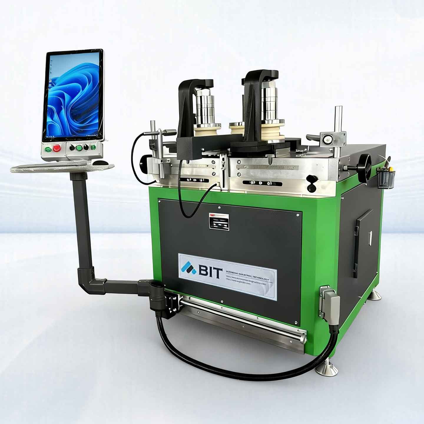
AXON-Servo 15
CNC Profile Bending Machine
Reinforced CNC Aluminum Bending | 15-Ton Thrust & Triple-Servo Torque. 50mm shaft diameter with optional integrated laser radius measurement auto-correction. Master complex multi-radius Window Frame Profile bending with zero-scratch precision and perfect consistency for high-end architectural extrusions.
About AXON-Servo 15
CNC Profile Bending Machine
The AXON-Servo 15 is the enhanced version of the AXON-Servo 12, specifically engineered for the high-efficiency forming of medium-sized aluminum extrusions. This model features a reinforced 50 mm shaft diameter and an upgraded X-axis bending force of 15 tons. Its Y-axis is powered by three independent servo-driven motors, delivering significantly higher bending force and superior torque. As the definitive model in the AXON-Servo series—balancing raw power with extreme precision—it can be equipped with an optional Laser Radius Measurement and Correction System, ensuring consistent accuracy for demanding industrial applications.
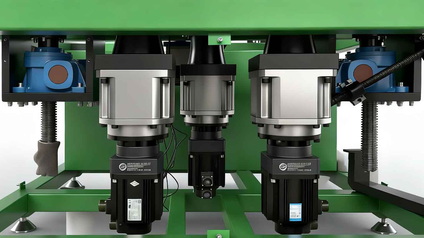
- Full Servo Drive System: Synchronized control of feeding (X-axis) and rotation (Y-axis). The Y-axis is powered by three independent servo motors, delivering significantly higher bending force and superior torque for optimized power distribution.
- 15-Ton Bending Thrust: Enhanced forming capability designed for larger cross-sections of thermal break profiles and industrial aluminum extrusions.
- Advanced 3D Bending: Features integrated Z-axis control with support for direct DXF/STEP file import. The CNC system automatically generates bending programs for complex 3D spatial geometries.
- ±0.01mm Repeatability: High-precision positioning combined with intelligent springback compensation ensures maximum consistency across high-volume production.
- Triple-Axis Independent Drive: Advanced CNC control for seamless multi-radius continuous bending, allowing smooth transitions between varying arcs.
- Optional Laser Correction System: Available with an integrated Laser Radius Measurement & Correction System, providing real-time monitoring and automatic adjustment to eliminate material variations.
- Zero-Scratch Surface Protection: Specialized tooling and micro-adjustment pressure control ensure that architectural finishes remain flawless during the bending process.
STRATOS & AXON-Servo
Technical Data for High-End Aluminum Extrusions
| Model | AXON-Servo 12 | AXON-Servo 15 | AXON-Servo 25 | STRATOS 30 | STRATOS 40 | STRATOS 70 |
|---|---|---|---|---|---|---|
| X-axis | ||||||
| Max. Force X-axis (t) | 13 | 15 | 25 | 30 | 40 | 70 |
| Position Accuracy (mm) | ≤0.01 | ≤0.01 | ≤0.01 | ≤0.02 | ≤0.02 | ≤0.02 |
| Driver | Servo Motor * 1 | Servo Motor * 1 | Servo Motor * 1 | Servo Hydraulic* 1 | Servo Hydraulic * 1 | Servo Hydraulic * 1 |
| Stroke Distance (mm) | 200 | 200 | 350 | 300 | 350 | 600 |
| Max. Insertion Width (mm) | 120 | 120 | 200 | 200 | 250 | 530 |
| Hydraulic Oil Volume (L) | – | – | – | 60 | 100 | 300 |
| Y-axis | ||||||
| Shaft Drive | Servo Motor * 3 | Servo Motor * 3 | Servo Motor * 3 | Servo Motor * 3 | Servo Motor * 3 | Servo Motor * 3 |
| Dyn. Shaft Speed Ctrl. (rpm) | 1-15/ (Cust.) | 1-15/ (Cust.) | 1-15/ (Cust.) | 1-15/ (Cust.) | 1-15/ (Cust.) | 1-15/ (Cust.) |
| Torque (Nm) | 3,500 | 6,000 | 6,000 | 8,000 | 11,000 | 30,000 |
| Shaft Height / Custom (mm) | 200 | 200 | 250 | 250 | 300 | 500 |
| Shaft Dia Ø (mm) | 50 | 60 | 80 | 80 | 105 | 150 |
| Deflection Corrector/Supports | Standard | Standard | Standard | Standard | Standard | Standard |
| Front Shaft Distance (mm) | 280-600 | 280-600 | 270-600 | 400-1200/3D | 400-800 | 450~1100 | 680~1600 |
| Z-Axis | ||||||
| CNC-Control | – | Optional | Optional | – | Optional | Optional |
| Force X-axis (t) | – | 5 | 10 | – | 10 | 15 |
| Position Accuracy (mm) | – | 0.1 | 0.1 | – | 0.1 | 0.1 |
| Lifting Distance | – | 0-120 | 0-150 | – | 0-150 | 0-200 |
| Driver | – | Servo Motor*2 | Servo Motor*2 | – | Servo Motor*2 | Servo Motor*2 |
| Control / Software | ||||||
| Flexible Panels | Standard | Standard | Standard | Standard | Standard | Standard |
| CNC System | Standard | Standard | Standard | Standard | Standard | Standard |
| Language | CN / EN / RU | CN / EN / RU | CN / EN / RU | CN / EN / RU | CN / EN / RU | CN / EN / RU |
| IPC / Industrial Control *1 | Optional | Optional | Optional | Optional | Optional | Optional |
| Laser Radius Measure*2 | – | Optional | Optional | Optional | Optional | Optional |
| Capacity | ||||||
| Min. Bending R (mm) | 100 | 100 | 100 | 150 | 150 | 250 |
| Max. Rolls Dia (mm) | 240 | 240 | 400/500 3D | 400 | 600 | 1000 |
| Max. W Bending (mm) | 120 (H: 60) | 120 (H: 80) | 200 (H: 80) | 200 (W: 90) | 300 (H: 80) | 300 (H: 160) |
| Max. H Bending (mm) | 200 (W: 40) | 200 (W: 50) | 250 (W: 65) | 250 (W: 70) | 300 (W: 80) | 500 (W: 100) |
AXON-Servo 15: High-Precision Solutions for Aluminium Window Frame Bending
Now, normally, when people think of bending metal, they imagine a large, sweaty man with a hammer making a terrible racket. But when we’re dealing with architectural aluminum, that sort of ham-fisted approach is, frankly, a disaster. It requires a bit of mechanical sympathy and, dare I say, some actual finesse.
Here is how to tackle these four specific challenges without making a complete dog’s breakfast of it.
1. Aluminium Window Frame Profiles: The “Jam Sandwich” Conundrum
Now, we must spend a proper amount of time on this because, frankly, it’s the most complicated of the lot. When you look at a modern, high-end window frame, you aren’t just looking at a piece of metal. You’re looking at a Thermal Break Profile.
The Problem: This is essentially an engineering sandwich: an outer aluminum skin and an inner aluminum skin, held together by a PA66 nylon insulation strip. The trouble starts the moment you try to bend it. You see, the outer part of the curve wants to stretch, and the inner part wants to compress. If you use a primitive machine, the stress focuses entirely on that plastic thermal bridge. It will snap, pop out, or—worst of all—the whole profile will twist like a damp fusilli pasta. It’s a mechanical nightmare.
Furthermore, these frames are usually anodized or powder-coated. If you scuff the surface, you can’t just “buff it out.” It’s ruined. And then there’s the issue of the “hollow section” collapsing. If the internal walls aren’t supported, the beautiful rectangular profile turns into a sad, squashed D-shape.
The Solution: This is where the AXON-Servo 15 proves it’s a proper bit of kit. First, it uses Triple-Axis Independent Drives. This is crucial. Because each roller is driven by its own servo motor, the machine can actually compensate for the speed differential between the inner and outer rings. It’s not just shoving the metal through; it’s coaxing it, which significantly reduces the shear stress on that delicate thermal bridge.
Secondly, we use Specialized Combined Tooling. We design “grooved” rollers that lock the insulation strip in place so it can’t migrate. We also use non-metallic materials—special polymers—so there’s no metal-on-metal violence. No scratches, no tears.
Finally, there is the CNC Springback Compensation. Aluminum has a memory; it wants to boing back to being straight. The AXON senses the material’s resistance and adjusts the pressure in real-time. It’s methodical, it’s logical, and it means the window frame actually fits the hole in the wall. Which is helpful.
2. Demountable Partition Wall Systems
The Problem: These are the long, elegant dividers you see in posh offices. The challenge here is Long-Distance Consistency. If the curve is slightly off at the beginning of a five-meter run, by the time you reach the end, the glass panel won’t fit into the track. It’s deeply embarrassing for everyone involved.
The Solution: The AXON’s ±0.01mm repeatability is the hero here. It ensures the radius is mathematically constant from the first millimeter to the last. We use a “Zero-Scratch” setup because these profiles are always at eye level—you simply cannot have a single mark on them.
3. Cable Tray Profile Bending
The Problem: These are the workhorses. They are wider, heavier, and have much more “heft.” The challenge is maintaining the Parallelism of the Sidewalls. In a heavy bend, the “U” channel wants to flare out or buckle inwards. If that happens, the snap-on lids won’t fit, and the electrician will start using colorful language.
The Solution: You need the 15 tons of thrust from the AXON-Servo 15. It provides the brute strength needed for these larger sections, but because it’s a servo system, it’s controlled strength. It keeps the base flat and the walls upright. It’s sensible engineering.
4. Spiral Coiling Rolling Shutter Profiles
The Problem: This is where things get properly 3D. A rolling shutter profile isn’t just a circle; it’s a spiral—a “coil.” If your machine only understands two dimensions, the profile will just hit itself as it comes around. You’ll end up with a jammed shutter and a very annoyed shopkeeper.
The Solution: This is where the Z-axis control comes in. By importing a DXF or STEP file, the CNC system automatically calculates the vertical lift required for the spiral. It manages the 3D trajectory so the profile coils smoothly and consistently, like a perfectly wound spring. It’s a triumph of mathematics over chaos.
There you have it. Four complicated problems solved with a bit of logic and a very well-engineered machine. Now, if you’ll excuse me, I’ve noticed my spirit level is slightly out of alignment, and it’s bothering me. Good day.
FAQ: Aluminum Profile Bending for LED Fixtures
Q1: How to choose the most suitable aluminium alloy and temper for architectural profiles?
A: Most architectural profiles utilize 6063-T5 due to its ideal balance between structural strength and formability. For applications requiring extreme radii, T4 temper is recommended for its superior ductility; once formed, the parts can undergo artificial aging to restore their full mechanical properties.
Q2: Which is better: bending before or after surface treatment (anodizing/powder coating)?
A: Standard practice suggests bending first and coating later to prevent “crazing” or micro-cracking on pre-coated surfaces. However, with BIT’s optimized tooling solutions, we can successfully bend pre-finished profiles while maintaining surface integrity, avoiding the common pitfalls of coating damage.
Q3: How to prevent hollow window profiles from collapsing or deforming during the bending process?
A: Hollow sections often require internal support, such as flexible nylon fillers, sand, or low-melting-point alloys, to prevent sidewall buckling. BIT provides complimentary tooling design, utilizing specialized dies and mandrels to ensure the structural integrity of complex, multi-cavity profiles.
Q4: What is the typical minimum bending radius for aluminium window frames?
A: To avoid material failure, the bending radius should generally be 3 to 5 times the profile thickness. For large industrial extrusions, while the minimum radius depends on the specific geometry, it can be precisely controlled down to 300 mm with our technology.
Q5: What is the primary accuracy challenge when bending partition wall profiles?
A: The main challenges are length consistency and joint alignment. Since partitions involve long sections, even a tiny springback variance can prevent glass panels from seating correctly. Our ±0.01mm repeatability ensures high batch consistency for seamless on-site installation.
Q6: How to ensure a scratch-free finish on high-end anodized office partitions?
A: For visual-critical components, we utilize non-metallic polymer tooling and precision servo-pressure control. This eliminates metal-on-metal contact and pressure marks, achieving a flawless “zero-scratch” decorative surface.
Q7: How to prevent sidewall inward deformation when bending large cross-section cable trays?
A: U-shaped or C-shaped channels are prone to instability under stress. By utilizing the 15-ton thrust of the AXON-Servo combined with specialized lateral support dies, we ensure the sidewalls remain vertical and the base remains flat throughout the bend.
Q8: How to improve efficiency and reduce labor for thick-walled industrial cable trays?
A: Our triple-axis independent servo drives provide superior torque, enabling single-pass forming of heavy-duty profiles. This significantly reduces cycle times compared to multi-pass methods and lowers the overall operational burden.
Q9: What are the technical challenges of spiral coiling for rolling shutter profiles?
A: The challenge lies in transitioning from 2D to 3D. Without precise vertical displacement control, the profile will collide with itself during the second rotation. An integrated Z-axis control system is required to guide the profile vertically for a perfect spiral trajectory.
Q10: How to simplify the programming process for complex spiral shutters?
A: By supporting direct DXF/STEP file imports, the CNC system automatically calculates the 3D path based on the CAD model. This eliminates manual coordinate entry and ensures the pitch perfectly matches the storage housing dimensions.