
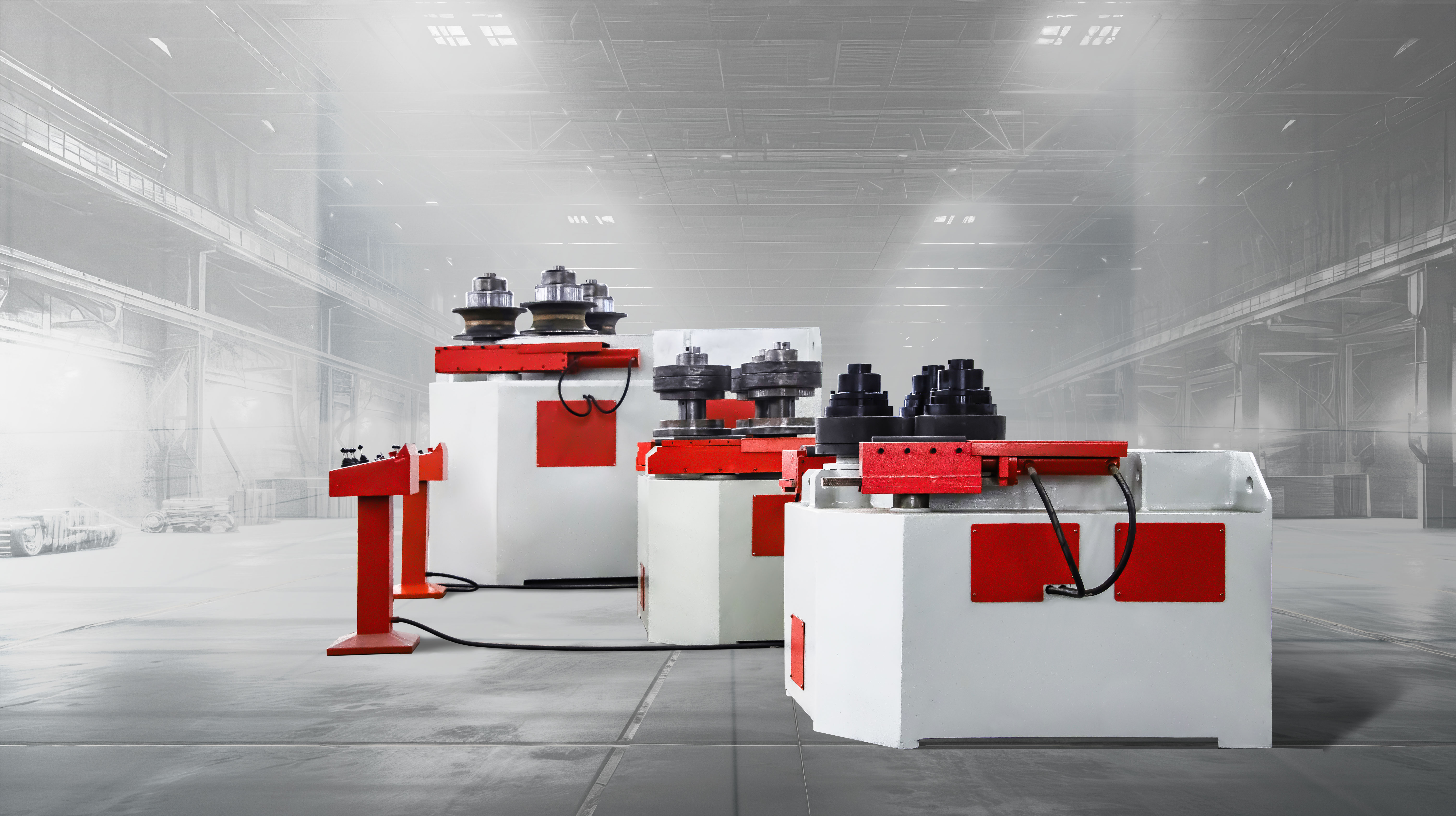
Profile Bending Machine
Precision Redefined: Perfect CNC Profile Rolling for Every Curve
What is
Profile Bending Machine?
For cold-bended structural sections (aluminum or steel), common technologies include Profile Rolling Machines, Stretch Forming Presses, Craft Formers, and Freeform Benders.
(Small Note: In industry parlance, “Profile Bending Machine” typically refers to the Profile Rolling Machine.)
The Profile Rolling Machine is a precision-engineered cold-rolling solution designed to shape a wide array of metal sections. Featuring robust rollers capable of processing aluminum, steel, and advanced alloys, it delivers consistent circular, semi-circular, or complex arched geometries with industrial-grade accuracy.
30+ years. BIT provides a CNC Profile Bending Machine for big mass-producing profile curved parts. We adopt high accuracy servo hydraulics and motors for profile bending machines.
The Profile Bending Machine is named as Section Bending Machine, Section Rolling Machine, Profile Rolling Machine, Angle Roller, Angle Iron Roller and Section Bender.
Types of
Profile Bending Machine
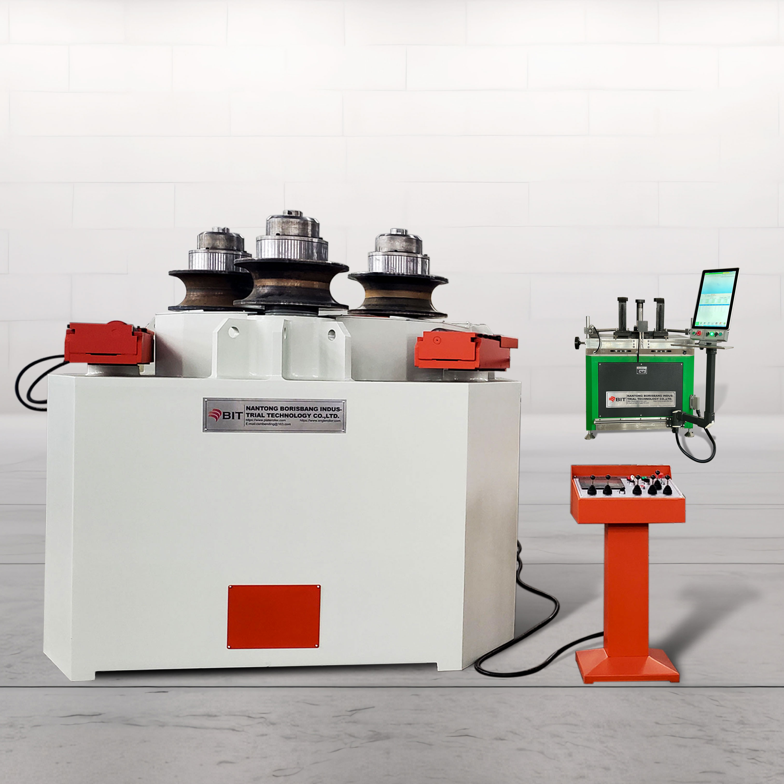
Depending on the application, our PBA (View Capacity Table)and PBC (View Capacity Table). series vary in construction and precision. While the standard machine is a 3-roller, we also offer customized 4-roller solutions to meet your specific needs.
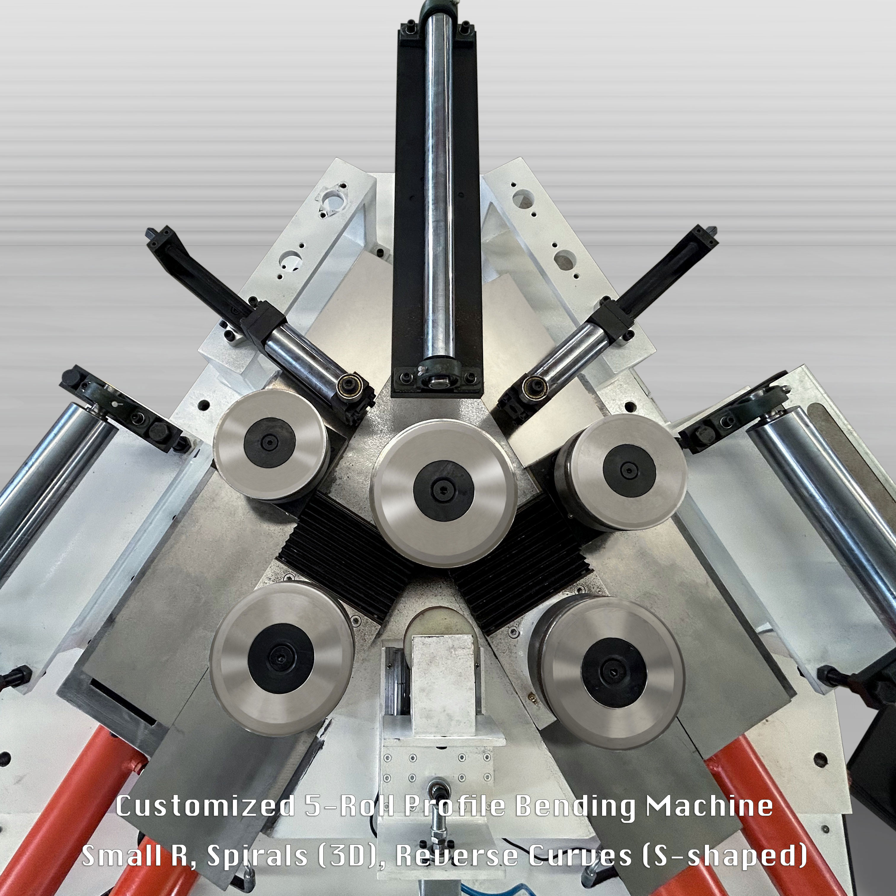
Roller Configuration: 3-Rolls: The industry standard for versatility and reliability across most applications. 4-Rolls: Designed for enhanced precision with superior material clamping and significantly reduced flat ends. 5-Rolls: Less common, engineered for specific high-precision complex profiles.
Control System: Manual Control: Direct operator interface, ideal for simple tasks or small-scale fabrication. PLC & CNC Control: A fully automated, high-precision system designed for complex geometries, multi-radius bending, and spiral shapes.
Driving System: Electric Motor Drive: Light to medium-duty tasks. Hydraulic Drive: Delivers max. power and torque for heavy-duty structural steel and large-scale sections. Servo Motor Drive: Provides high-speed, high-precision performance with superior energy efficiency—ideal for aluminum extrusions. Servo-Hydraulic Drive: Combining the massive power of hydraulics with the pinpoint precision and energy efficiency of servo control.
Bending Geometry: Pyramidal: A classic design where the top roll moves vertically; ideal for standard symmetrical bending. Single Pinch: Features one adjustable side roll, allowing for better pre-bending of one end of the profile. Double Pinch: Both side rolls move independently, allowing for the highest precision and the ability to pre-bend both ends in a single pass.
Machine Orientation: Vertical Type: A compact, space-saving design. Horizontal Type: The preferred orientation for extra-large, heavy, or ultra-long profiles to prevent gravitational distortion during the bending process.
Bending Accuracy
The PB Series Profile Bending Machine provides perfect profile bending and the highest bending accuracy and is used in various industries and fields that require the highest production quality.
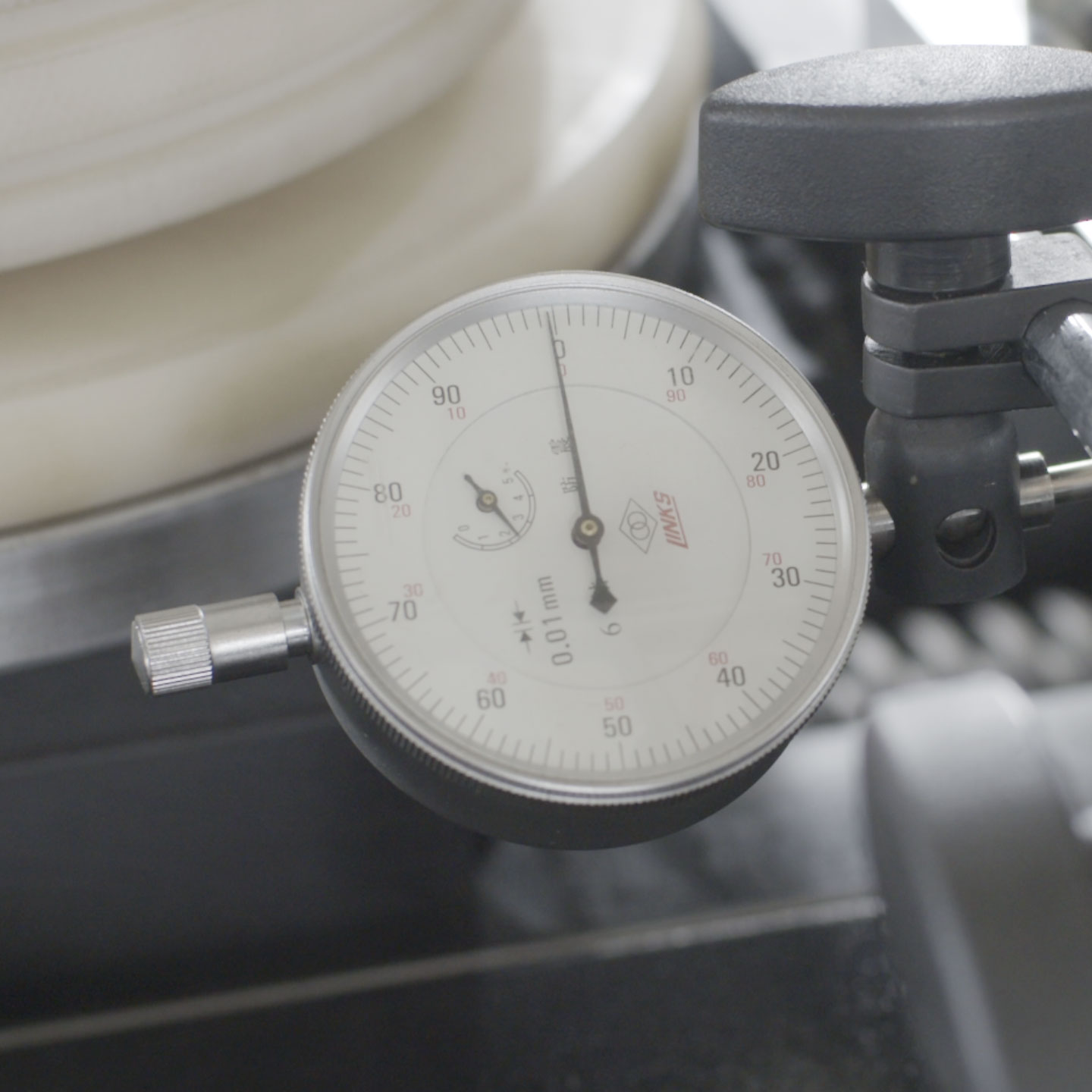
Precision Control: Laser Compensation: Integrated system for real-time radius measurement and automatic spring-back coefficient storage. Repeat Position Accuracy: 0.01mm (PBA) / 0.02mm (PBC), guaranteeing identical output for high-volume production batches.
Surface Integrity: Speed Micro-Adjustment: 0.1 mm/s precision feed to eliminate impact marks and surface scuffing. Electronic Sync: All-axis differential control with < 0.1% sliding friction, preventing Galling on polished stainless or decorative aluminum.
CNC Tracking: Eliminates roller slippage for pinpoint arc length and multi-radius transition accuracy.
BIT Tooling: High-Speed Protection: Specialized tooling design that maintains surface integrity at maximum bending speeds. Industrial Scale: Ensures “zero-damage” surface quality on large-scale workpieces without compromising throughput.
Uses of
Profile Bending Machine
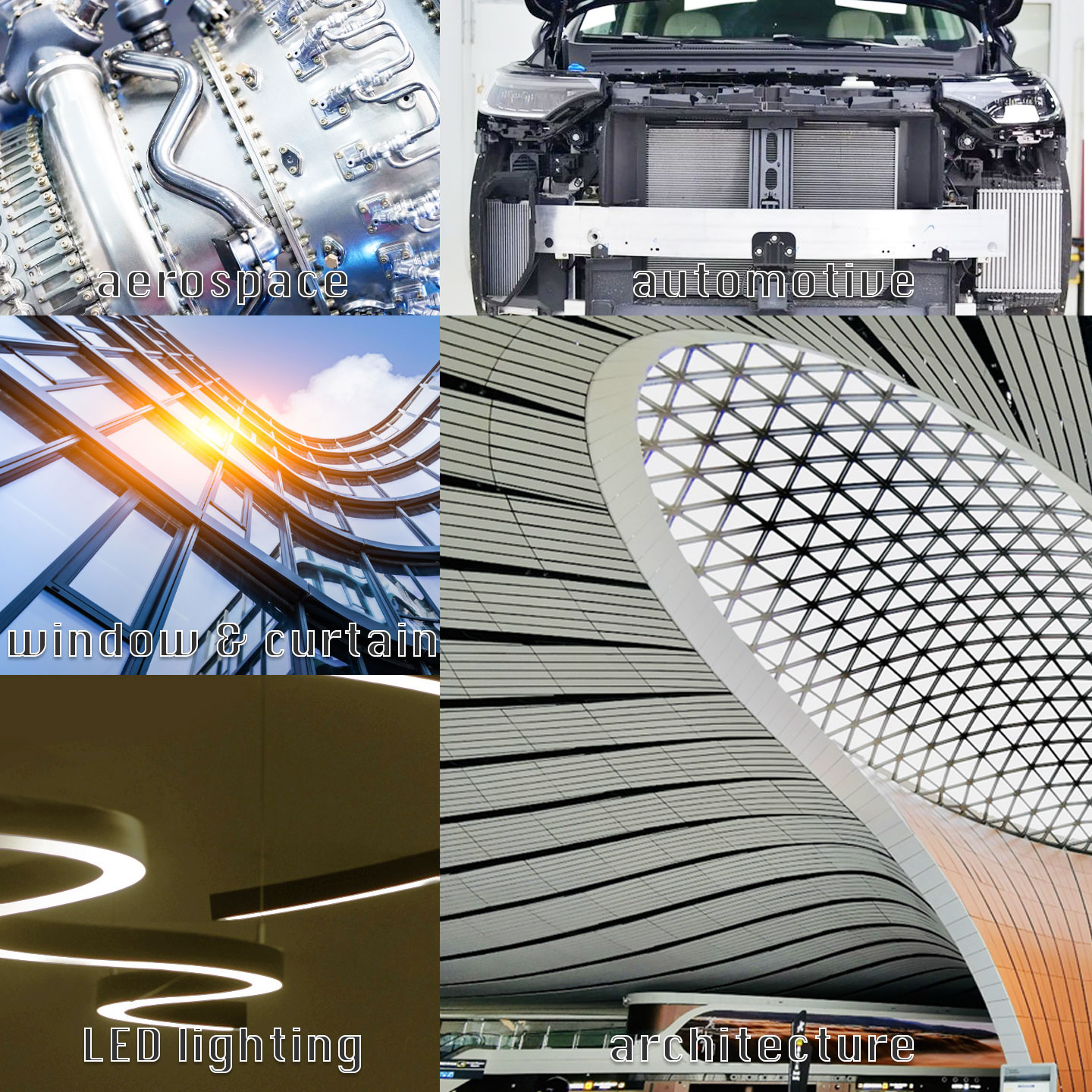
Profile bending machines offer versatile cold-forming solutions for a wide range of materials—from aluminum and copper extrusions to hot-rolled structural steel sections—producing perfectly curved workpieces for diverse industries:
The PBA Series is the ideal choice for high-precision forming of aluminum extrusions, engineered specifically for processes demanding ultimate accuracy; meanwhile, the PBC Series excels in bending a wide range of heavy-duty structural metal profiles, easily handling angle iron, flat bars, pipes (including spiral tubes), and various large-scale structural beams, such as T-beams, I-beams (IPE), H-beams (HEA, HEB, ISMB), and U-channels.
Architecture & Curtain Walls: Curved aluminum windows and doors, circular curtain wall frames, skylight structures, arched sunrooms, curved beams, and architectural facades.
Transportation & Automotive: High-speed train body components, arched roof beams, interior structural parts, crash beams (impact bars), roof frames, luggage racks, and door reinforcement sections.
Heavy Industry & Machinery: Mining conveyor components, mechanical equipment frames, nuclear power structural supports, oil and gas pipelines, large-scale structural steel sections, and industrial piping.
Furniture, Commercial & Decor: Curved railings, display racks, decorative metal elements, lighting fixtures, artistic sculptures, and furniture frames.
Sports & Public Facilities: Arched beams for stadiums and arenas, public seating structures, and landscape architectural elements.
Shipbuilding & Marine: Hull framing, safety handrails, and deck structural components.
Aerospace: Fuselage frames, wing ribs, cabin door structures, and high-precision components with strict springback control requirements.
What are the
Construction & Features?
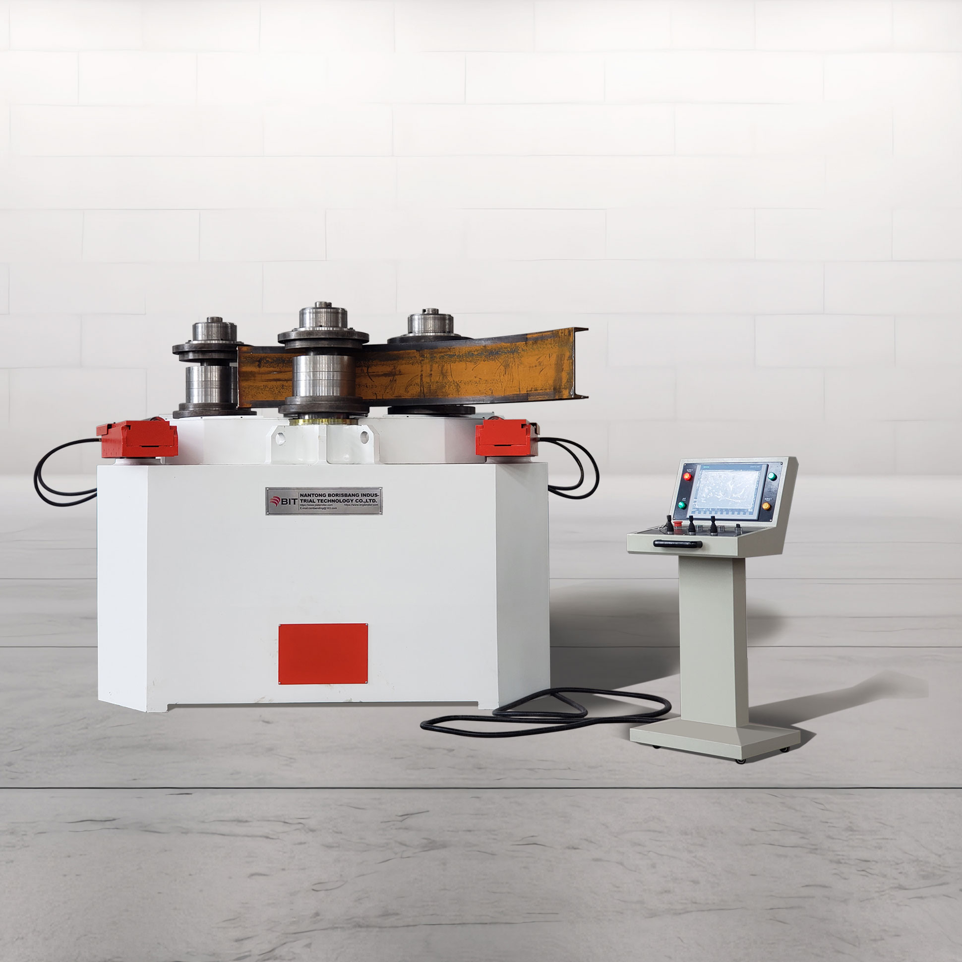
The profile bending machine integrates a rigid frame, precision spindle system, modular rolls, electro-hydraulic or servo drives, and CNC control.
The high-precision PB Series CNC profile bending machine is controlled by a motion control system and driven by either servo motors (aluminum extrusion workpieces) or a servo-hydraulic system (heavy-duty bending), enabling accurate bending of both standard and complex curves that excels in both high-precision aluminum forming and heavy-duty structural steel processing.
Frame: Closed-loop frame design enhances bending and torsional rigidity for stable performance under demanding conditions.
Spindle System: Spindles are made from through-hardened 42CrMo alloy steel and precision-ground. The rigid support structure withstands axial and radial loads during bending.
Modular Tooling: Rollers (HRC 55–60) use a segmented modular design, allowing flexible configuration for various profile cross-sections.
Drive System: X and Y axes use electro-hydraulic proportional or fully electric servo drives, depending on configuration. The Z-axis enables multi-axis interpolation for 3D curve forming.
NC Intelligence: Based on PLC or CNC architecture, supporting multi-axis synchronization and parametric programming. Includes material database and springback compensation, with optional radius measurement for real-time correction.
Leveraging 30 years of expertise, this machine combines intuitive CNC control with high-torque multi-axis drive to achieve ultra-tight radii and complex 3D shapes without cracks or deformation.
How it Works?
When the material properties permit, the PB series profile bending machine’s high torque enables single-pass bending, eliminating multiple forming steps and significantly improving efficiency.
The PB Profile Bending Machine utilizes CNC automation to achieve simple three-point bending of complex shapes, enabling the most cost-effective cold roll-bending with high precision and efficiency: Easy Operation, Low Costs, and Reduced Assembly.
Pre-Bending Preparation: The profile is positioned in the rolling area. DXF/STEP files are imported via the CNC system (manual parameter input is also available). The system generates the bending path and initializes process parameters.
Initial Positioning: Displacement sensors calibrate the initial roller position to ensure alignment with the theoretical model. Clamping and Pre-Bending: The upper or side roller feeds radially to clamp the profile. The servo system provides stepless pressure or flow control to start pre-bending.
Incremental Rolling: Three rollers rotate synchronously, driving the profile by friction. The CNC system adjusts roller feed after each pass, gradually reducing the bending radius. Single-pass forming is possible depending on material and section properties.
Measurement and Compensation: Laser or displacement sensors measure actual dimensions and curvature. The system calculates springback and performs final correction to achieve the target shape.
Retraction and Reset: The rollers retract to the home (initial) position, the clamping force is released, and the machine resets, preparing for the next rolling cycle.
Customer









Partnerships That Grow
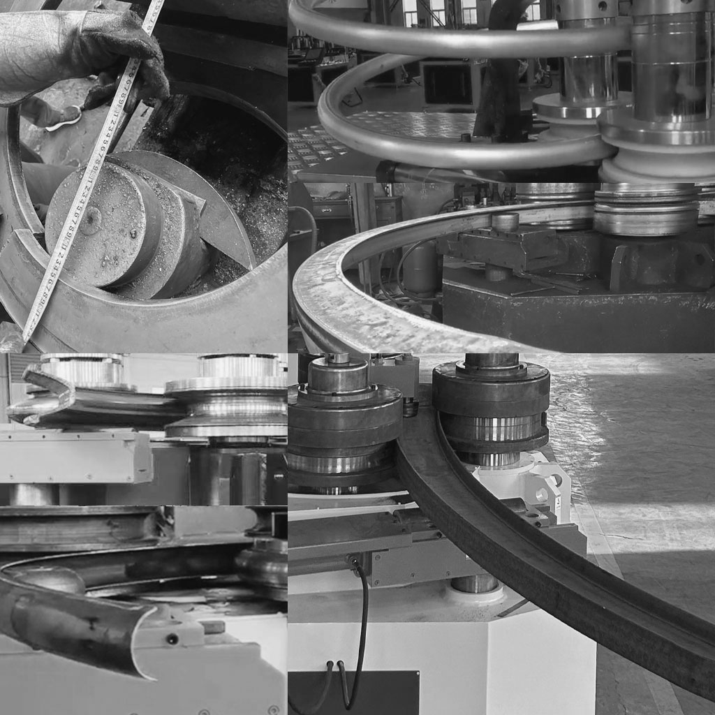
In China, we maintain long-term and stable win-win partnerships with several bending factories, growing together. As our partners’ businesses expand, they have successively purchased multiple machines, ranging from light to heavy-duty profile bending machines.
- Driven by customer collaboration, practical innovations create perfect profile bending.
- Same model, same power, greater bending capacity (compared to competitors).
- Complete tool configuration ensures no deformation of the section (e.g., angle bending device).
- Servo motor drive for aluminum bending ensures consistent bending workpieces, consistent line speed and high torque. (China patent protected, PBA).
- Variable Geometry Rolls: Minimizes unbend ends and achieves precise bends with small radii. (China patent protected, PBA).
- 30+ Years of Bend Tool Design: offering perfect solutions, No Section Deformation, No Surface Wrinkles, and No Cracking.
About US
Profile bending machines for aluminum and carbon steel are among our key products. Over 1,000 world-renowned companies, including Sany, Zoomlion, Fuyao, and BYD, have chosen our solutions.
Borisbang Industrial Technology (BIT) specializes in profile bending machines and other metal cold bending machinery.
With a highly trained technical team and a diverse range of quality machines, including profile bending machines, plate rolling machines, fluid cell presses, and 3D freeform tube benders, we deliver excellence. Our commitment to on-time deliveries and customer satisfaction has earned us a loyal global client base.
FAQ & VOTERS
Why is a Profile Bending Machine also called a Section Bending Machine or Angle Roll?
They refer to the same type of roll bending equipment. The naming variation comes from regional habits, structural steel terminology, and historical usage.
Section Bending Machine (European & Structural Engineering Context)
- Background: In European and British structural engineering, standardized steel components (angles, channels, I-beams, RHS/SHS tubing) are categorized as Structural Sections.
- Naming Logic: Focuses on the machine’s function of continuously bending metal bars defined by specific cross-sectional profiles.
Profile Bending Machine (American & Multi-Industry Context)
- Background: In US terminology and general manufacturing, Profile encompasses all non-flat rolled or extruded shapes, ranging from industrial aluminum extrusions to custom rolled sections.
- Naming Logic: Emphasizes machine adaptability for shaping diverse structural and custom profiles via interchangeable roll tooling.
Angle Roll / Angle Roller (Historical & Workshop Colloquialism)
- Background: Historically, early roll bending machines were dedicated primarily to bending angle iron, utilizing fixed angle-bending dies.
- Naming Logic: Serves as a legacy shop-floor term (synecdoche). Despite modern machines handling diverse geometries, fabricators across North America routinely retain “Angle Roll” or “Angle Bender” as standard trade jargon.
Why does the term “Profile Bending Machine” specifically refer to Roll Bending equipment rather than Rotary Draw, Stretch Bending, or Hydroforming?
While various processes can bend metal profiles, the term Profile Bending Machine explicitly denotes 3-roll or 4-roll continuous rolling equipment due to three key differences:
- Universal Tooling Versatility: Roll benders handle nearly all cross-sectional geometries (angles, channels, beams, tubes, extrusions) on a single machine by adjusting modular roll sets, making them the true “profile generalists.”
- Continuous 3-Point Rolling (No Fixed Radius Dies): Unlike Rotary Draw benders or Hydroforming presses—which require exact-radius dedicated dies for each bend—roll benders continuously adjust roll positions to form multiple radii, spirals, or full 360° rings flexibly.
- Distinct Process Designations: Equipment utilizing distinct mechanical principles has established specific industry terms. Rotary Draw machines focus on pipe/tube work (Tube Benders), stretch-forming systems emphasize tension control (Stretch Benders), and high-frequency hammer-shaping units focus on local deformation (Shrinker-Stretchers or Kraftformers).
What is the main difference between a standard Profile Bending Machine and machine-powered hand-forming tools like the Kraftformer when bending angle steel and profiles?
While both machines can bend metal profiles, they operate on completely different principles, distinguishing automated rolling from operator-guided craftsmanship:
- Profile Bending Machine (Continuous Roll Bending — Fully Mechanical):The machine uses motor- or hydraulically-driven rollers to auto-feed and continuously roll long profiles. Bending is achieved through preset roller positions imposing a macro-bending moment across the entire length. It is built for high-efficiency, repeatable, and large-scale production of standard arcs, rings, and spirals.
- Eckold Kraftformer (High-Frequency Hammering — Machine-Powered Hand Bending):The machine provides high-frequency reciprocating hammer strokes, while the feeding speed, angle, and bending line are entirely guided by the operator’s hands using feel and experience. By applying localized shrinking or stretching directly to the flange of an angle iron or profile, it acts as a power-assisted hand-forming process. It is uniquely suited for complex 3D contours, custom prototype work, precise stress-relief adjustments, and fine correction without fixed tooling.
Q: What are the primary causes of minimum bend radius limitations and cross-sectional deformation in profile bending, and what are the industry-standard solutions?
Achieving tight bend radii (R) without structural failure and maintaining cross-sectional integrity (preventing buckling, wrinkling, flattening, or web distortion) are the two most critical quality targets in profile bending. The root causes and engineering solutions are structured below:
- Material Limits & Cracking (Tight Radius vs. Material Ductility)
- The Challenge: High-yield or low-ductility metals subjected to tight cold bending experience excessive tensile stress on the outer radius, leading to cracking or severe elastic springback.
- Thermal & Induction Bending Solution: High-frequency induction coils locally heat the deformation zone in real time. This lowers the material’s yield strength and boosts elongation, enabling ultra-tight radii without structural cracking.
- Geometric Instability & Collapse (Thin-Walled or Asymmetrical Profiles)
- The Challenge: Asymmetrical sections (e.g., angle iron, channels, I-beams) or hollow extrusions experience uneven stress distribution across tension and compression zones, causing wall collapse, web buckling, or twisting.
- External Mechanical Support Solution: For structural steel like IPE/HEB or angle iron (in leg-in/leg-out configurations), hydraulic traction units and 3-axis adjustable guide rollers clamp the flanges and webs to counteract twisting moments and prevent lateral distortion.
- Internal Cavity Support Solution: For thin-walled aluminum extrusions, inserting flexible PE mandrels, compacted sand, or low-melting-point rosin/alloys provides internal opposing pressure to prevent wall collapse.
- Internal High-Pressure Forming (Hydroforming): The most advanced and high-cost option—pressurized fluid inside a closed mold supports the interior walls, producing precise, zero-collapse complex 3D profiles for aerospace and high-end automotive applications.
How do Leg-In vs. Leg-Out orientations affect angle iron bending, and how do guide rollers prevent cross-sectional twisting and collapse?
Q: How do Leg-In vs. Leg-Out orientations affect angle iron bending, and how do guide rollers prevent cross-sectional twisting and collapse?
A: Bending asymmetrical profiles like angle iron inherently introduces cross-sectional instability due to unsymmetrical stress distribution. The specific deformation risks and mechanical solutions are structured below:
- Bending Orientations & Instability Behaviors:
- Leg-In / Toe-In Bending: The vertical leg faces inward toward the center of curvature. Under severe axial compression, the inner edge is highly susceptible to local web buckling or inward collapsing, while the outer leg tends to warp under tension.
- Leg-Out / Toe-Out Bending: The vertical leg faces outward. Although the vertical leg is in tension, its unconstrained free edge lacks torsional rigidity, triggering spiral twisting (torsional buckling) and flange angle distortion (opening or closing of the 90° angle).
- Role of 3-Axis Adjustable Guide Rollers (Anti-Twist Devices):
- Counteracting Torsional Buckling: Positioned on both sides of the main bending rolls, guide rollers clamp against the vertical and horizontal legs to apply direct lateral and vertical restraint, negating the coupled bending-torsion moments inherent to asymmetrical profiles.
- Preventing Cross-Sectional Collapse: By mechanically supporting the legs throughout the deformation zone, the rollers enforce strict 90° profile geometry without angle opening or buckling.
- Real-Time Spiral Correction: Positioned along the exit rolling path, the rollers adjust in three dimensions (up/down, in/out) to continuously push twisting profiles back into a true flat plane.
- Recommended Demonstration Video: For a visual demonstration comparing Leg-In versus Leg-Out rolling techniques and observing guide rollers in action, watch Angle Rolling Process: Leg Out and Leg In. https://youtu.be/w6ulBmUzZmw
Why do Profile Bending Machines have maximum size capacity limits on the X-axis (section height) and Y-axis (working shaft length)?
Capacity limits on both axes are dictated by separate mechanical and structural mechanics constraints:
X-Axis Limitations (Section Height / Depth)
- Geometric Interference: The center distance between shafts and roller diameter physically limit clearance. Oversized profiles collide with adjacent rollers, shafts, or machine frames.
- Exponential Torque Requirements: Section modulus (Zx) grows cubically with height. Expanding shaft center distance (L) creates space, but proportionally increases the total bending moment (M = F · L / 4), requiring exponentially higher hydraulic force and driving torque.
Y-Axis Limitations (Shaft Working Length / Width)
- Cantilever Shaft Deflection (δ ∝ L3): Bending shafts function primarily as cantilevered beams under heavy concentrated loads. Deflection increases cubically with working length (L3).
- Structural Consequences: Excessive deflection causes permanent shaft deformation, uneven roller clamping force (resulting in twisted or flared profiles), and severe bearing edge-loading that leads to premature failure.
Architectural Note (Why Cantilever Design Wins)
- While closing both frame ends—like a Plate Roll—would eliminate Y-axis deflection, Profile Bending Machines must retain an open-cantilever shaft design to allow rapid roll tooling changes and clear space for 3-axis anti-twist guide rollers.