AXON-Servo 12
CNC Profile Bending Machine
AXON-Servo 12 offers precision bending for LED frame aluminum extrusions. Master complex S-shapes and tight radii with zero-scratch servo control. BIT provides integrated solutions for architectural lighting profiles, ensuring flawless surface quality and high repeatability.
About AXON-Servo 12
CNC Profile Bending Machine
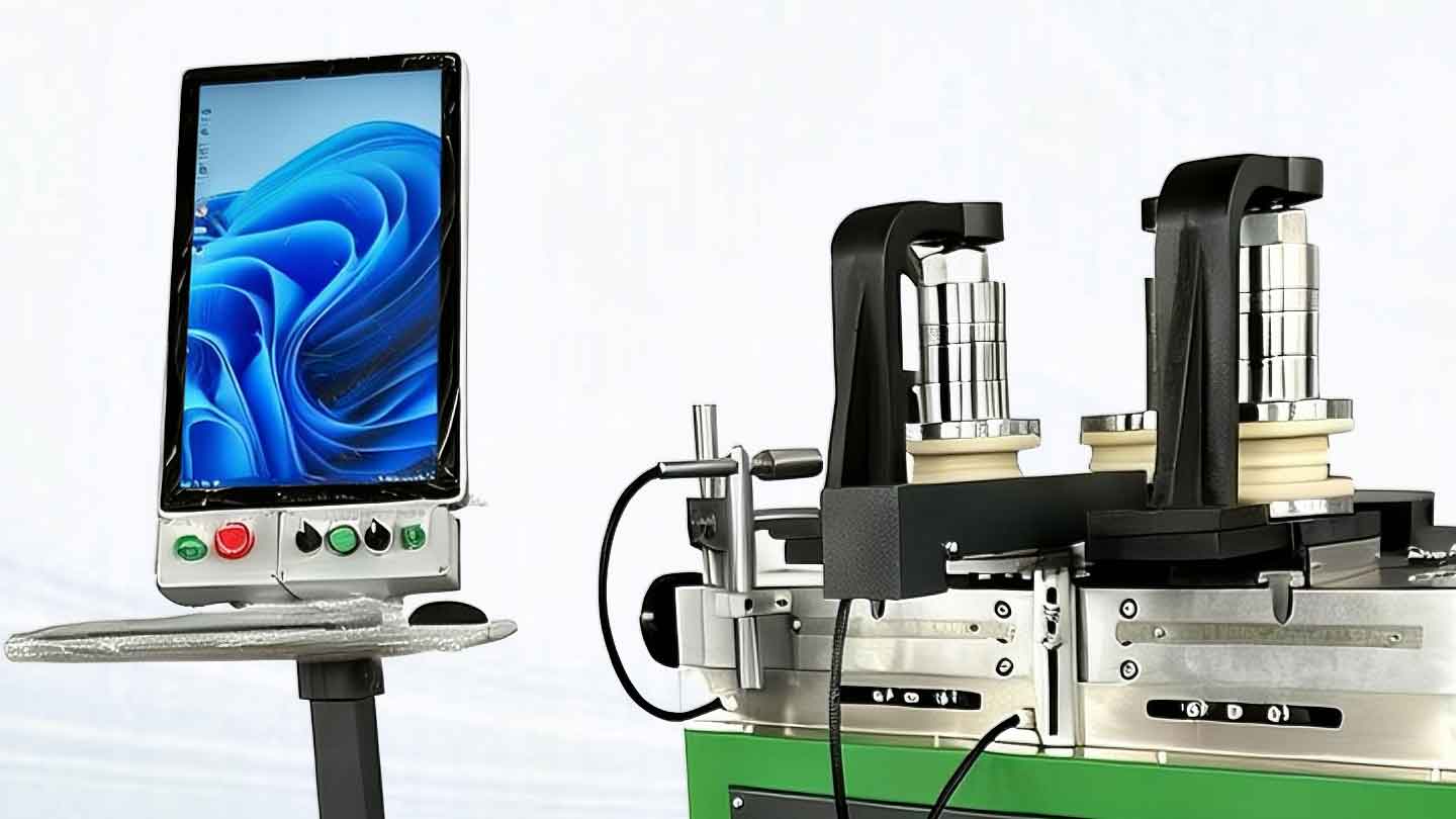
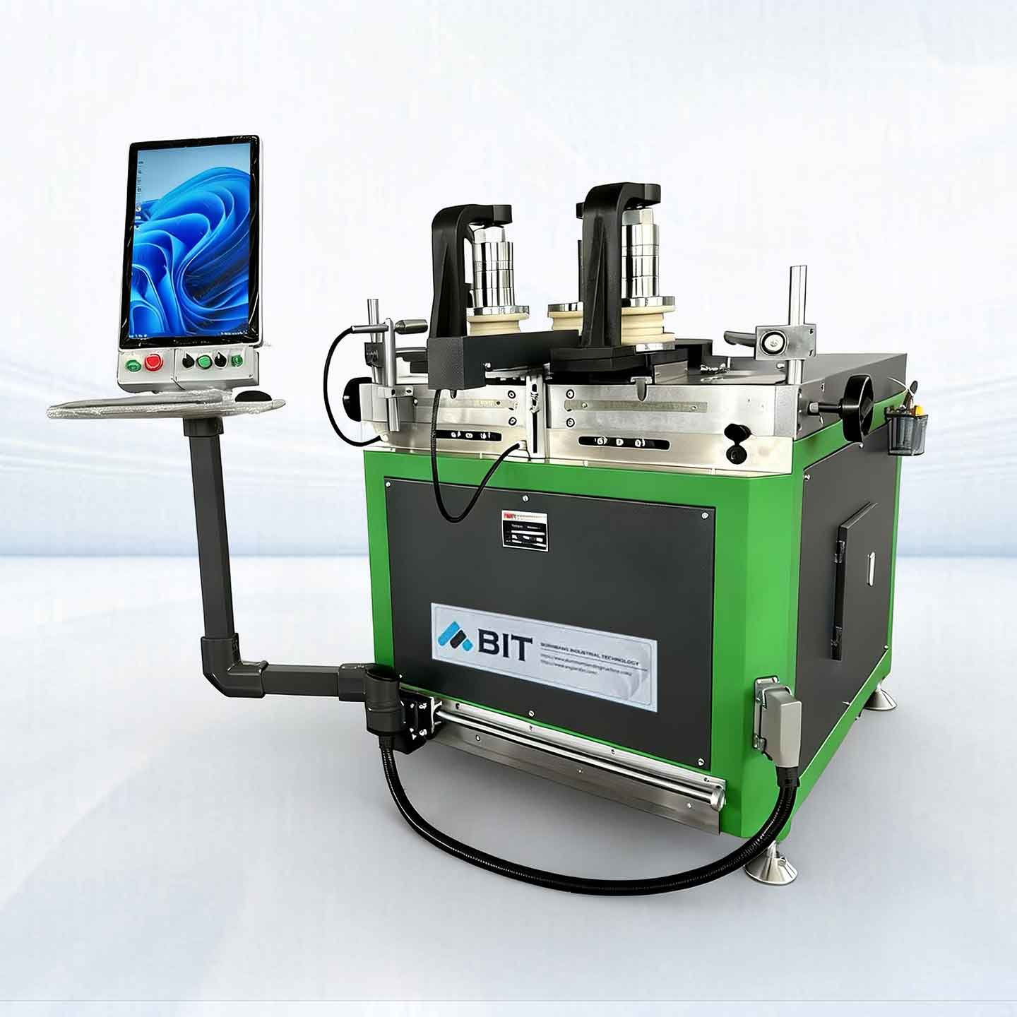
The AXON-Servo 12 is the ideal solution for bending small steel or aluminum profiles, such as LED lighting frames, especially in restricted workspaces. This model features a full-servo drive architecture: both the X-axis (feeding) and Y-axis (rotation) are driven by high-performance servo motors, delivering a robust 12-ton bending force. As a standard across the AXON-Servo series, it achieves a superior X-axis repeatability of ≤0.01 mm, ensuring maximum precision and consistency for high-volume aluminum bending projects.
- Servo-controlled X-axis (bending axis): precise downward force application via servo-motor drive ensuring accurate positioning and repeatable bending results
- Front shaft distance: min. 200 mm (optionally reduced for tight bending radii)
- The Y-axis independently driven by synchronized servo motors: smooth and quiet operation with dynamic speed control, up to approx. 16 rpm
- High-precision CNC control system: with automatic path correction and springback compensation
- Bending direction away from the operator for enhanced operational safety
- Intelligent control system with DXF / STEP import and automatic generation of bending programs
STRATOS & AXON-Servo
Technical Data for High-End Aluminum Extrusions
| Model | AXON-Servo 12 | AXON-Servo 15 | AXON-Servo 25 | STRATOS 30 | STRATOS 40 | STRATOS 70 |
|---|---|---|---|---|---|---|
| X-axis | ||||||
| Max. Force X-axis (t) | 13 | 15 | 25 | 30 | 40 | 70 |
| Position Accuracy (mm) | ≤0.01 | ≤0.01 | ≤0.01 | ≤0.02 | ≤0.02 | ≤0.02 |
| Driver | Servo Motor * 1 | Servo Motor * 1 | Servo Motor * 1 | Servo Hydraulic* 1 | Servo Hydraulic * 1 | Servo Hydraulic * 1 |
| Stroke Distance (mm) | 200 | 200 | 350 | 300 | 350 | 600 |
| Max. Insertion Width (mm) | 120 | 120 | 200 | 200 | 250 | 530 |
| Hydraulic Oil Volume (L) | – | – | – | 60 | 100 | 300 |
| Y-axis | ||||||
| Shaft Drive | Servo Motor * 3 | Servo Motor * 3 | Servo Motor * 3 | Servo Motor * 3 | Servo Motor * 3 | Servo Motor * 3 |
| Dyn. Shaft Speed Ctrl. (rpm) | 1-15/ (Cust.) | 1-15/ (Cust.) | 1-15/ (Cust.) | 1-15/ (Cust.) | 1-15/ (Cust.) | 1-15/ (Cust.) |
| Torque (Nm) | 3,500 | 6,000 | 6,000 | 8,000 | 11,000 | 30,000 |
| Shaft Height / Custom (mm) | 200 | 200 | 250 | 250 | 300 | 500 |
| Shaft Dia Ø (mm) | 50 | 60 | 80 | 80 | 105 | 150 |
| Deflection Corrector/Supports | Standard | Standard | Standard | Standard | Standard | Standard |
| Front Shaft Distance (mm) | 280-600 | 280-600 | 270-600 | 400-1200/3D | 400-800 | 450~1100 | 680~1600 |
| Z-Axis | ||||||
| CNC-Control | – | Optional | Optional | – | Optional | Optional |
| Force X-axis (t) | – | 5 | 10 | – | 10 | 15 |
| Position Accuracy (mm) | – | 0.1 | 0.1 | – | 0.1 | 0.1 |
| Lifting Distance | – | 0-120 | 0-150 | – | 0-150 | 0-200 |
| Driver | – | Servo Motor*2 | Servo Motor*2 | – | Servo Motor*2 | Servo Motor*2 |
| Control / Software | ||||||
| Flexible Panels | Standard | Standard | Standard | Standard | Standard | Standard |
| CNC System | Standard | Standard | Standard | Standard | Standard | Standard |
| Language | CN / EN / RU | CN / EN / RU | CN / EN / RU | CN / EN / RU | CN / EN / RU | CN / EN / RU |
| IPC / Industrial Control *1 | Optional | Optional | Optional | Optional | Optional | Optional |
| Laser Radius Measure*2 | – | Optional | Optional | Optional | Optional | Optional |
| Capacity | ||||||
| Min. Bending R (mm) | 100 | 100 | 100 | 150 | 150 | 250 |
| Max. Rolls Dia (mm) | 240 | 240 | 400/500 3D | 400 | 600 | 1000 |
| Max. W Bending (mm) | 120 (H: 60) | 120 (H: 80) | 200 (H: 80) | 200 (W: 90) | 300 (H: 80) | 300 (H: 160) |
| Max. H Bending (mm) | 200 (W: 40) | 200 (W: 50) | 250 (W: 65) | 250 (W: 70) | 300 (W: 80) | 500 (W: 100) |
Advanced CNC Profile Bending for LED Lighting & Architectural Aluminum
Hello. I’m Lion, and if there’s one thing that really gets my gears turning—besides a perfectly sorted tool chest or a well-steeped pot of tea—it’s the marvelous engineering behind a properly bent piece of aluminum.
You see, most people look at a curved LED light or a window frame and think, “Oh, that’s a nice shape.” But they don’t understand the technical peril involved. It’s actually quite stressful.
Here is the situation, explained properly:
LED Fixture Aluminum extrusions: Precision and Surface Protection
Now, bending a thin-walled LED fixture extrusion is, frankly, a nightmare. If you’re not careful, the whole thing will ripple, wrinkle, or simply collapse like a soufflé in a thunderstorm. And because these bits are usually anodized or powder-coated, you can’t just buff out a scratch—there is absolutely zero tolerance for ham-fistedness. You have to be precise.
This is where the AXON-Servo 12 comes in. It uses full-servo micro-adjustment, which allows for incremental pressure control so delicate it wouldn’t bruise a peach. We’ve also designed specialized non-metallic tooling to ensure there’s no “metal-on-metal” unpleasantness. For the really thin, hollow bits, we use flexible internal supports—essentially giving the aluminum a spine—so the cross-section stays exactly as the designer intended. It’s methodical, and it works.
Mirror Frame Aluminum Profiles: Tight Radii and Closure Accuracy
When you’re making mirror frames, you’re dealing with incredibly tight radii and multi-segment arcs that have to meet up perfectly. If the closure is off by even a fraction of a millimeter, the whole thing is rubbish. The real enemy here is “springback.” You see, aluminum has a memory, and different batches of hardness mean it wants to boing back to a different shape every time.
The AXON series solves this with a standard springback compensation system. It’s a clever bit of kit that automatically adjusts the parameters so every frame closes with satisfying, Teutonic precision. Furthermore, the CNC system handles multi-radius bending in a single setup. It transitions from a straight line to a complex curve as smoothly as a Bristol 403 on a B-road. It’s quite lovely, really.
Small-to-Medium Thermal Break Profiles: Structural Integrity and Stability
Finally, we have the “Thermal Break” profile. This is a bit of an engineering sandwich: two pieces of aluminum joined by a PA66 insulation strip. The problem is that during a bend, the inner and outer sections want to move at different speeds. If you get it wrong, the insulation strip will snap or pop out, and you’re left with a twisted mess.
To fix this, you need to go slowly. The AXON-Servo uses three-axis independent drives to provide asymmetric power—basically compensating for that speed differential so the shear stress on the strip is minimized. We also use “grooved” support tooling to lock the thermal bridge in place. With 12 tons of thrust and high torque at low speeds, the machine just… eases it into shape. It’s a triumph of steady, sensible torque over brute force.
FAQ: Aluminum Profile Bending for LED Fixtures
Q1: How does CNC technology ensure consistency when bending large batches of LED profiles?
A: Traditional manual bending often struggles with uniformity due to material variations. CNC machinery solves this by using precise computer control and automated springback compensation. This ensures that every profile in a large batch remains consistent, typically maintaining tight tolerances of approximately ±0.01 mm to ±0.05 mm.
Q2: What types of shapes and materials can be processed for LED lighting fixtures?
A: While aluminum is the primary material used for its lightweight and thermal properties, CNC machines can handle various metals used in fixture manufacturing. By using specialized tooling and custom rollers, these profiles can be bent into a wide array of geometric shapes, including rectangles, triangles, ovals, and perfect circles.
Q3: How do advanced bending techniques prevent surface damage and profile distortion?
A: LED profiles are often thin-walled and sensitive. To prevent collapsing or surface marring, advanced techniques utilize customized internal supports and specialized tooling to hold the profile securely during deformation. This is crucial for maintaining the precise structural integrity required to fit LED diffusers and covers perfectly.
Q4: Can LED profiles be bent in different directions for varied lighting effects?
A: Yes. CNC bending offers the flexibility to bend profiles with the LED diffuser cover facing either inward or outward. This allows lighting designers to create solutions for both direct and indirect illumination, depending on the architectural requirements of the project.
Q5: What are the critical technical constraints to consider when bending LED aluminum profiles?
A: Successful bending depends on three primary technical factors: the Minimum Bending Radius, Material Temper, and Diffuser Compatibility. Every profile has a physical limit; exceeding the minimum radius will cause the channel to deform or the aluminum to crack. To prevent such failures in thin-walled extrusions, using the correct material temper (typically T3–T5) is essential for structural integrity. Finally, because standard rigid diffusers often cannot follow tight curves, specialized silicone or flexible covers are usually required to ensure a perfect fit in curved installations.