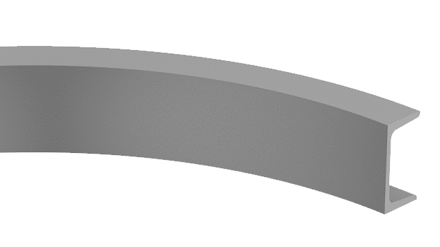
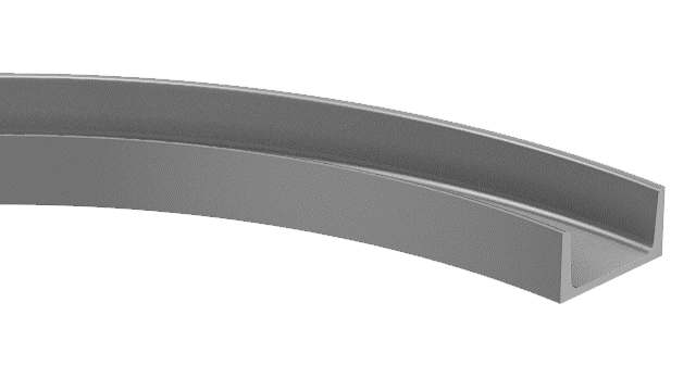
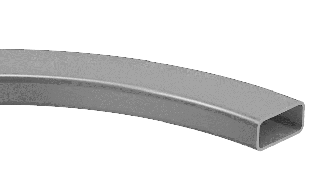
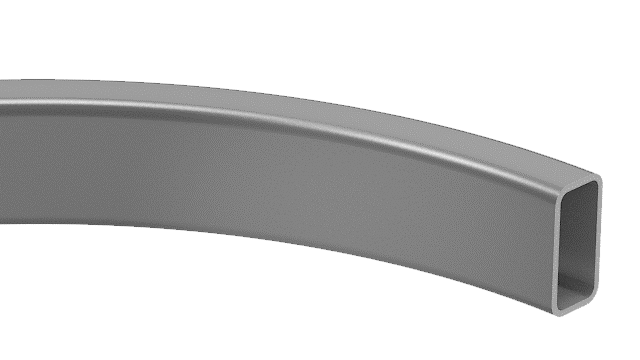
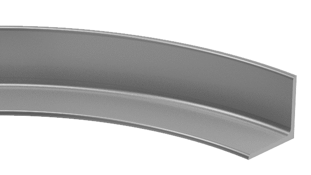
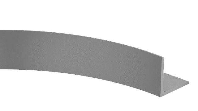
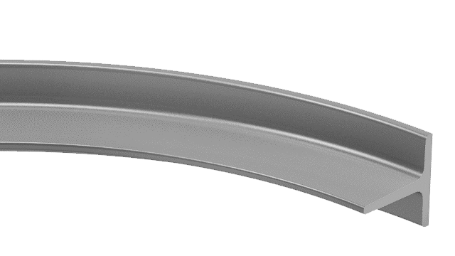
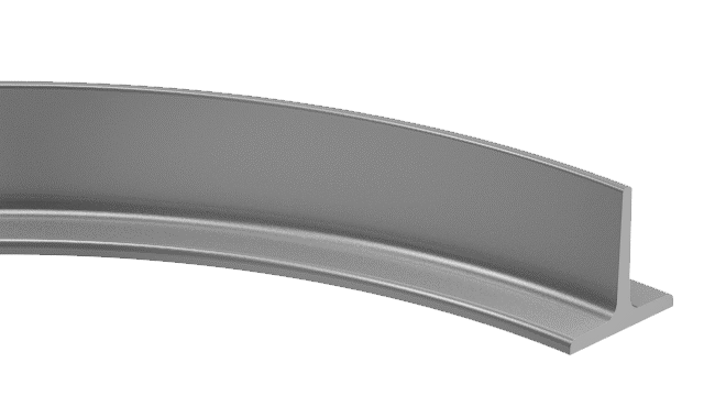
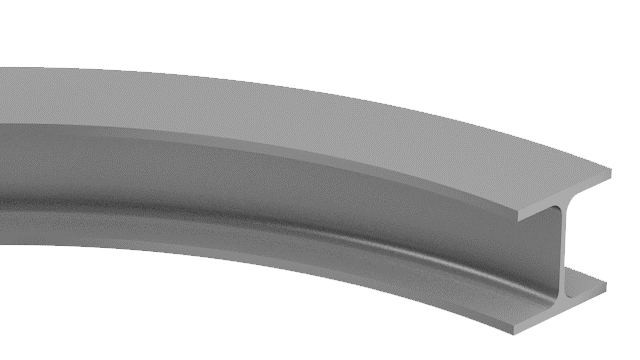
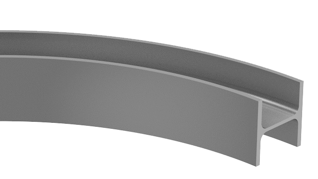
Roll bending C channel(also called U channel) profile with C channel bending machine(profile bending machine) is a metal forming process that involves passing C channel through a series of rollers to achieve a desired curve or bend without compromising the material’s structural integrity. For any form of C-shaped or U-shaped channel steel, there are only three ways to roll bending the channel profile, Y-Y axis flanches in, Y-Y axis flanches out, and X-X axis(hard way), as shown below:

PBC C Channel Bending Machine Rolls Settings for C Channel Bending
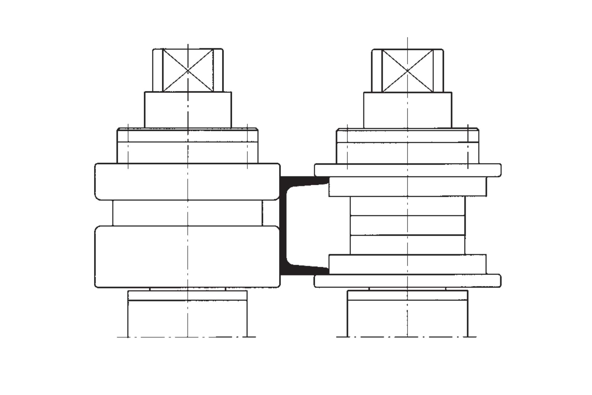
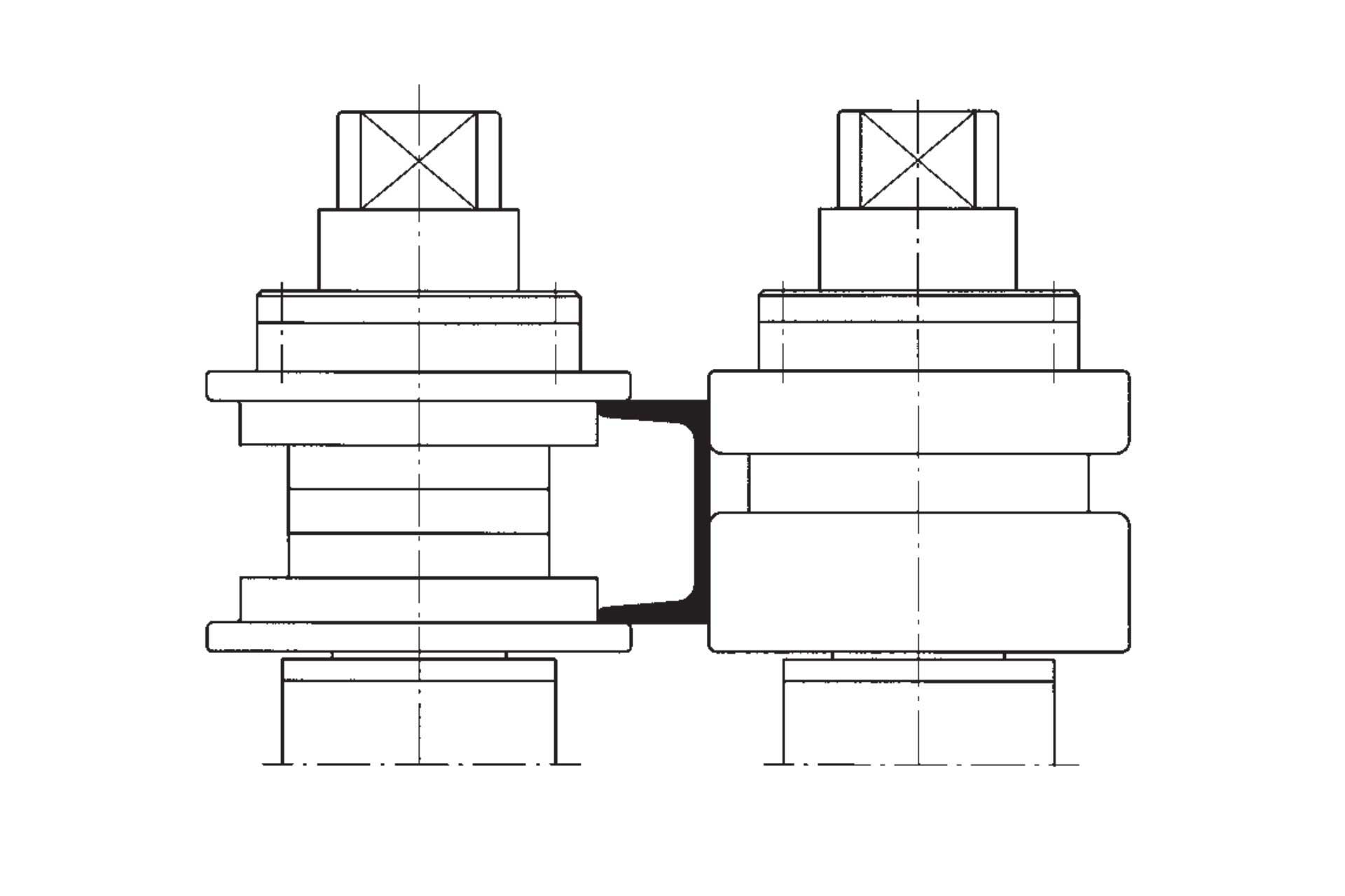
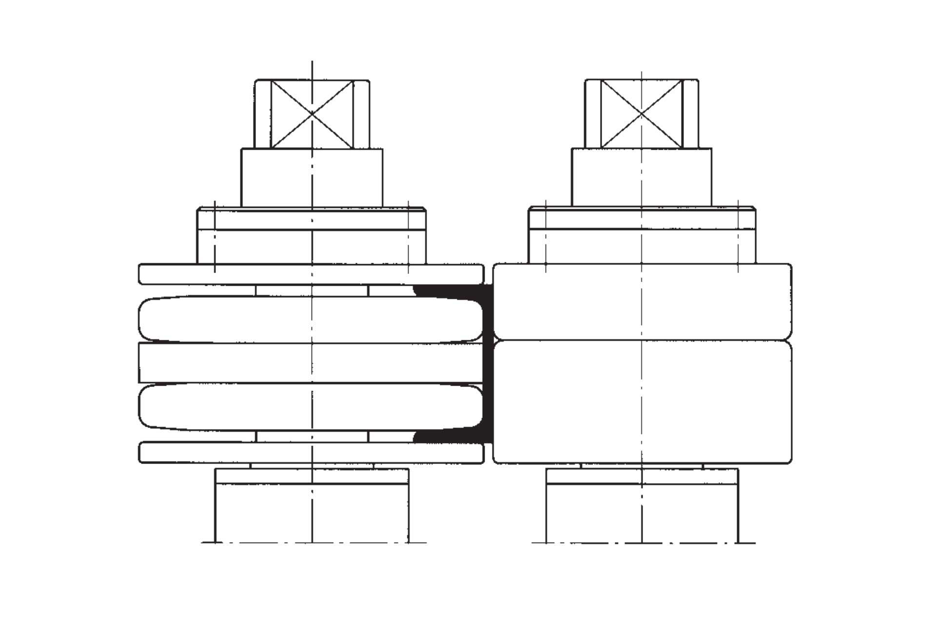
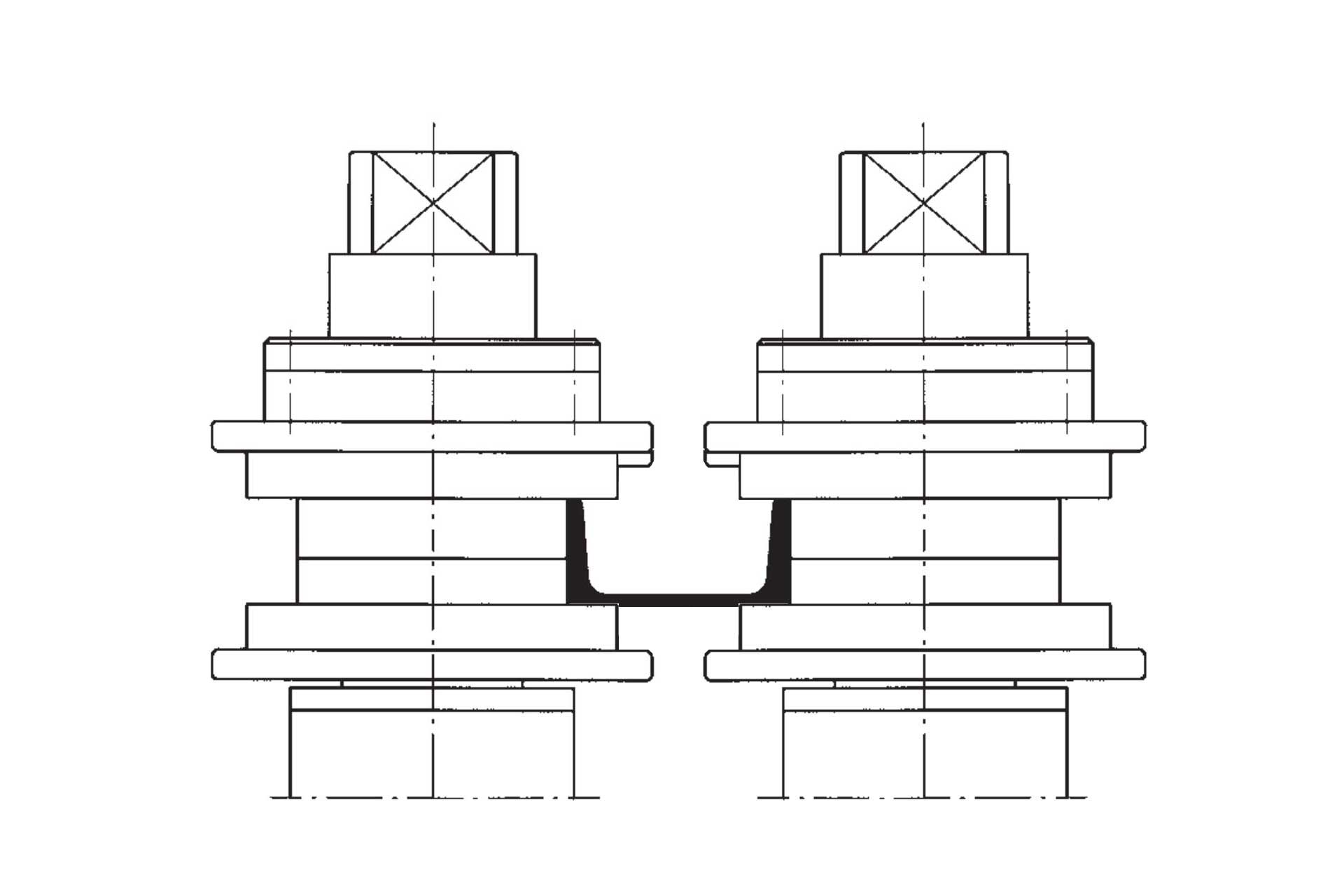
For C channel roll bending with Y-Y axis flanches in, Y-Y axis flanches out, for small quantities of workpieces, the universal profile bending rolls provided with the PBC profile bender can be used. If such roll bending is required for a long period of time, the machine must be equipped with bending rolls specially manufactured according to the commonly used C channel steel dimensions. Below is a diagram of the common roller settings for both bending methods, and a diagram of the special roller:

Hydraulic Pulling Apparatus for C Channel Bending
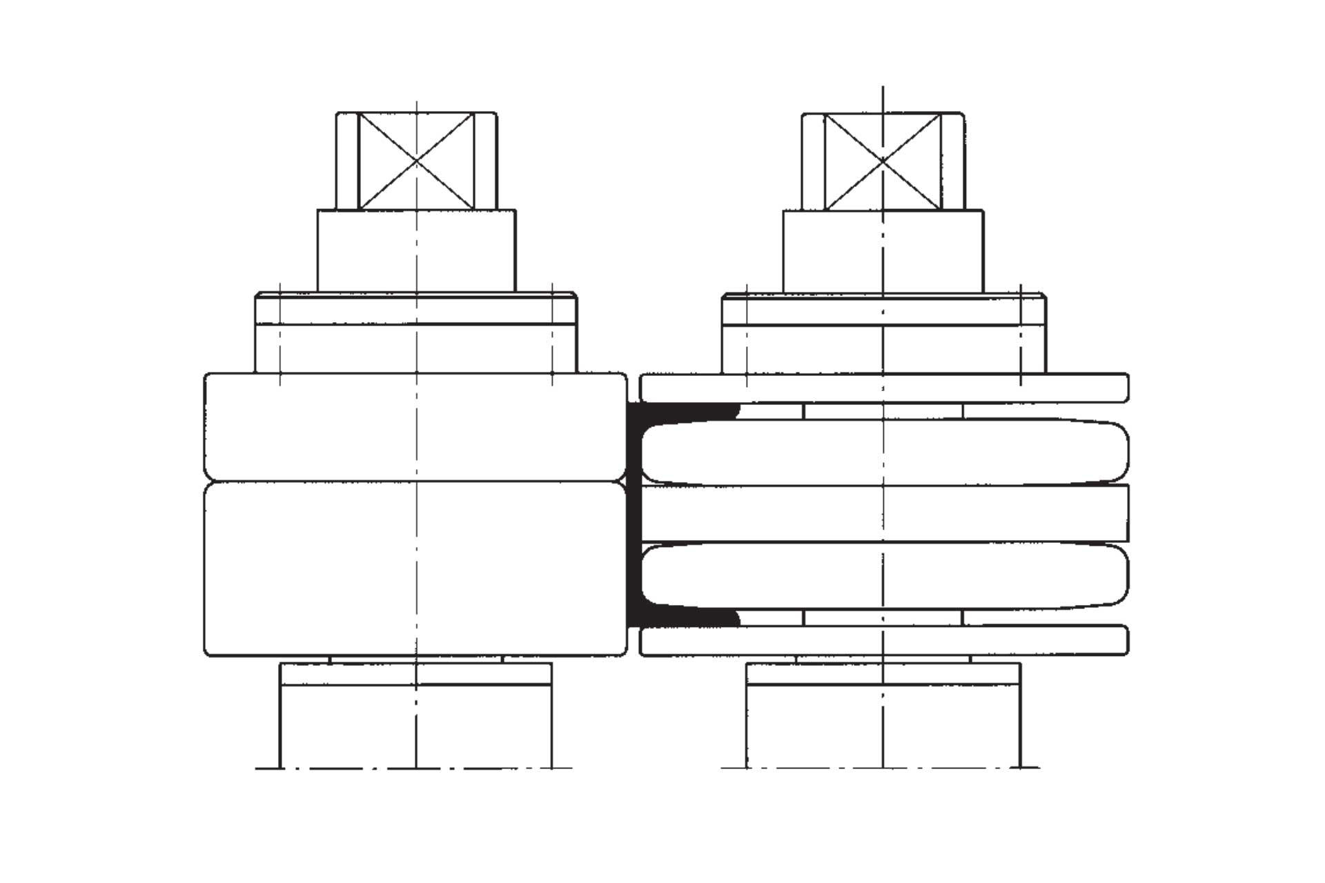
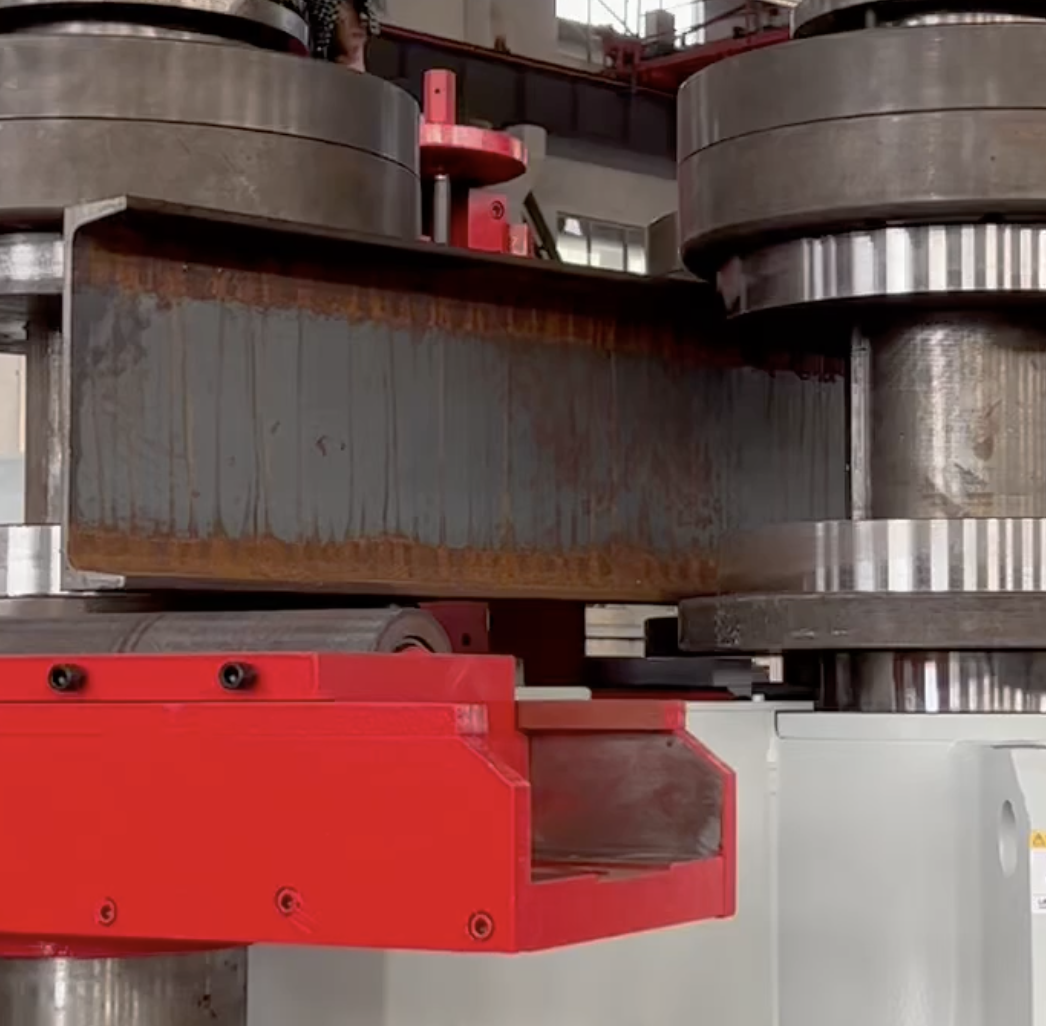
X-X Axis bending C Channel with PBC C Channel Bending Machine of the bending positions which requires more power than the others, because resisting moment, according to this neutral axis, increases remarkably. Standard rolls can be used, but they have to be settled so that mate rolls are against the machine as per drawing. At the same time, the hydraulic stretching device is used to prevent the web from deforming.
Profile Bending Machines for C channel bending can be configured to have additional Pulling Apparatus on the outside flange of the beam rolled the hard way. Roll bending I Beam with hard way must balance the compressive forces of the main three rolls with the tension supplied by the rolls pulling on the flange to keep the web from distorting as the beam is curved.
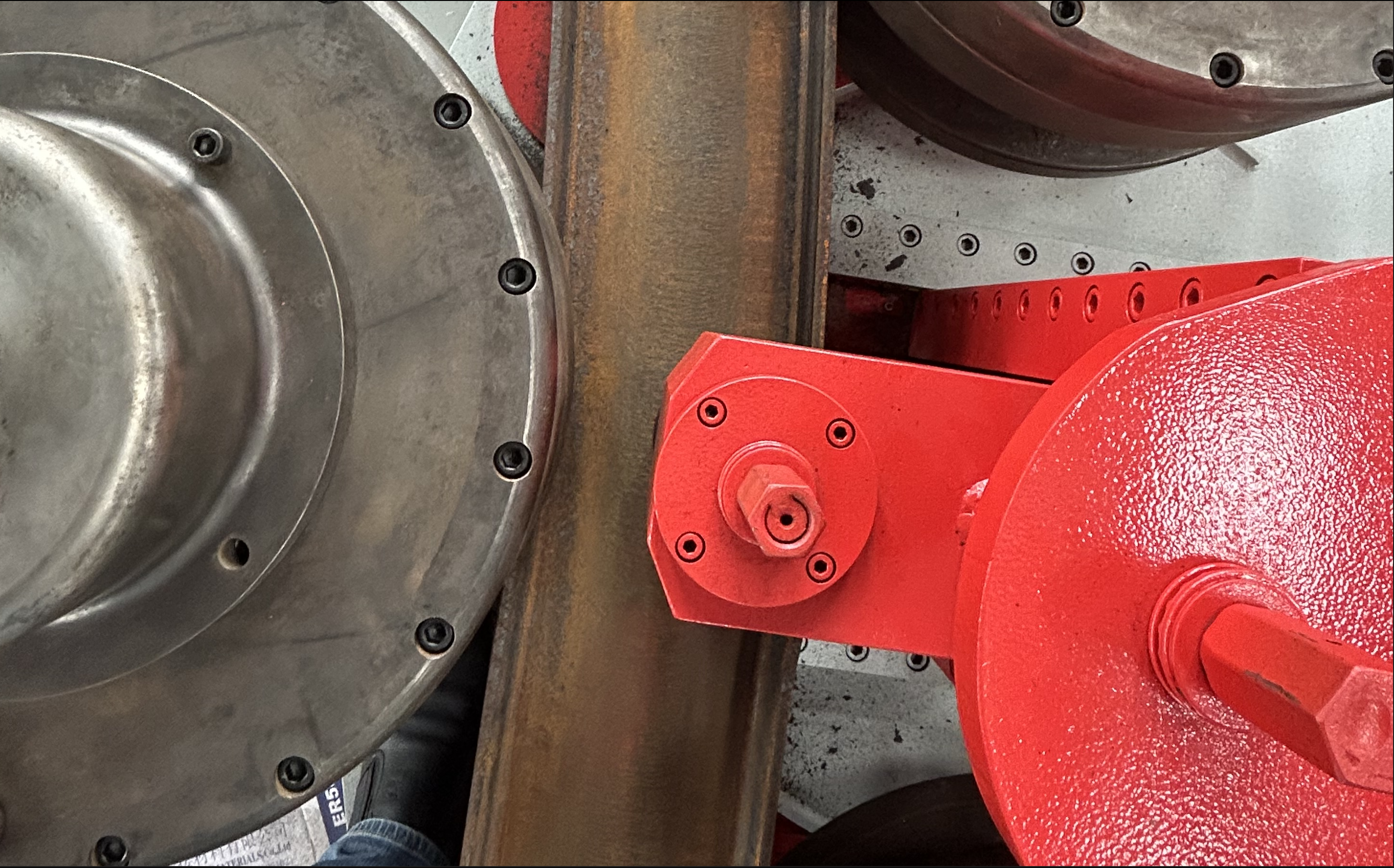
When is the Hydraulic Pulling Apparatus needed on a PBC C Channel Bending Machine?
When performing hard-way (X-X axis) roll bending of I-beams or U-shaped channels, the cross-section experiences highly uneven stress distribution. This is especially critical for profiles with thin webs and wide flanges, which are prone to web buckling, section twisting, or flange collapse under compressive force.
To tackle such challenging bending tasks, the PBC C Channel Bending Machine can be optionally equipped with a Hydraulic Pulling Apparatus. Its primary function is:
Working Principle: The hydraulic pulling device is installed on the outer flange of the I-beam or C channel. It applies precisely controlled and continuous tension via hydraulic cylinders. This tension, combined with the compressive force from the machine’s main three rolls, forms a balanced system of outer tension and inner compression, effectively maintaining the integrity of the profile during bending.
Basic Parameters of 3 Popular PBC C Channel Bending Machines
| Item | PBC 300 | PBC 360 | PBC 450 | PBC 500 | PBC 550 |
|---|---|---|---|---|---|
| Section Modulus (cm³) | 75-240 | 180-320 | |||
| Bending Speed (m/min) | 4.5 | 4.5 | 4.5 | 4.5 | 4.5 |
| Guide Rolls Moving Speed (m/min) | 1.6 | 1.6 | 1.6 | 1.6 | 1.6 |
| Upper Shaft Diameter (mm) | 180 | 220 | |||
| Lower Shaft Diameter (mm) | 160 | 180 | |||
| Bending Roller Diameter (mm) | 460 | 520 | |||
| Hydraulic Motor Power (kW) | 11.0 | 15.0 | |||
| Weight (kg) | 3600 | 5000 | |||
| Diameter (mm) | 2500×2530×1700 | 3200×2600×1800 | |||
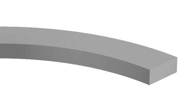
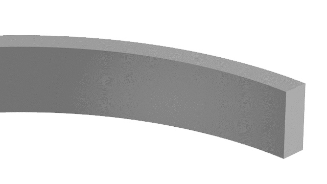
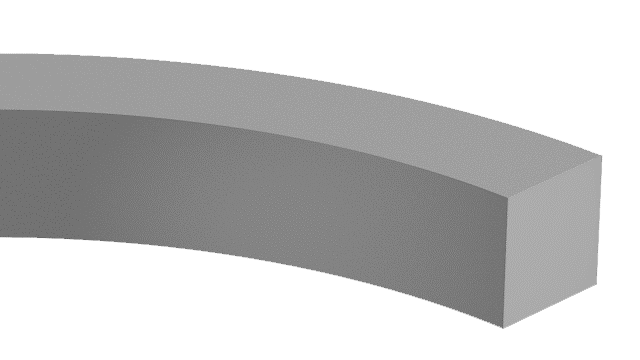
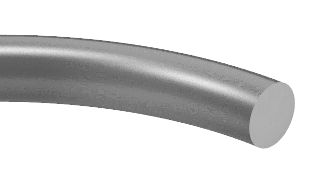
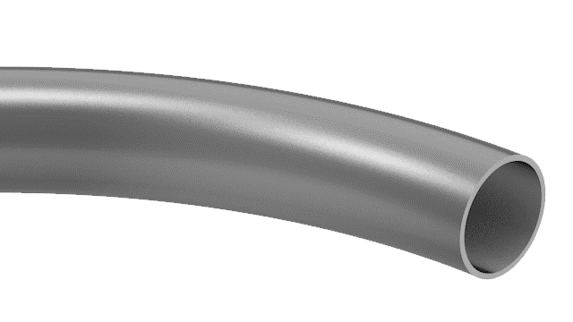
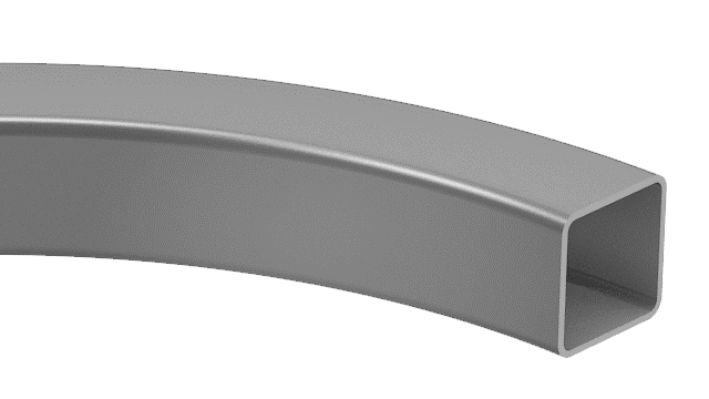
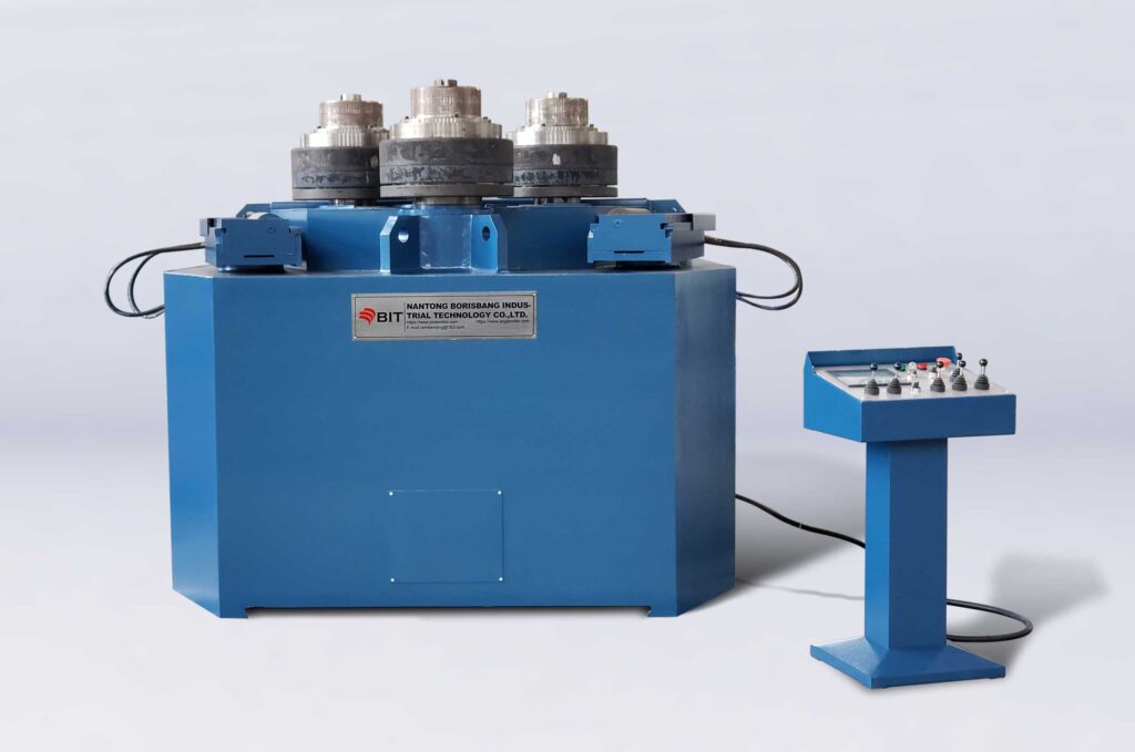 | 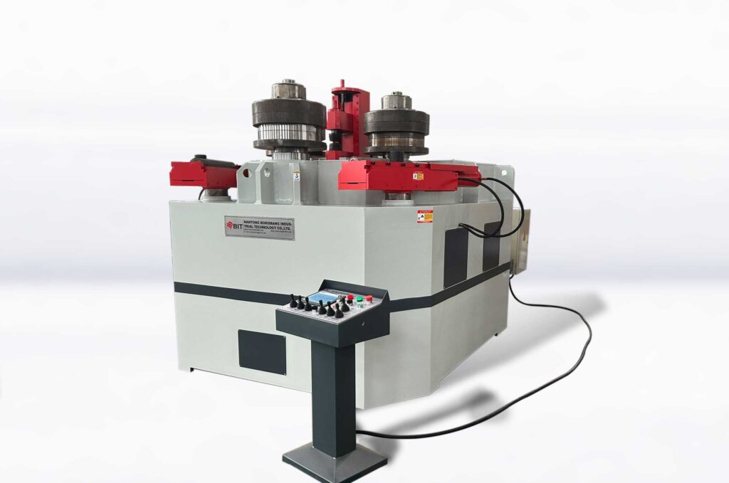 |  | 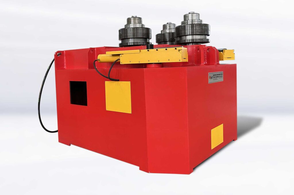 | 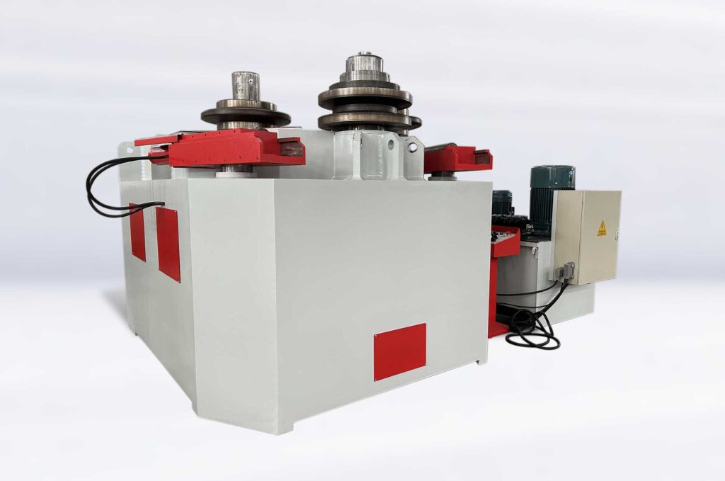 |
Capacity Table for Bent Profiles
| Profile & Bending Method | PBC-300 | PBC-360 | PBC-450 | PBC-500 | PBC-550 | Mold & Tool |
|---|---|---|---|---|---|---|
 | 150×30 Φ1500 | 175×40 Φ2500 | ○ | |||
 | 250×40 Φ1000 | 350×40 Φ1500 | ○● | |||
 | 80×80 Φ1500 | 110×110 Φ1600 | ○ | |||
 | Φ100 Φ1000 | Ø 125 Φ1200 | ● | |||
 | Φ170 Φ2000 | Φ190 Φ2500 | ● | |||
 | 120x120x8 Φ3000 | 150×150×8 Φ5000 | ○● | |||
 | H: max.60 W: max.120 Φ1500 | H: max.80 W: max.160 Φ5000 | ○● | |||
 | H: max.120 W: max.60 Φ1500 | H: max.160 W: max.120 Φ2500 | ○● | |||
 | 130x130x15 Φ1200 | 160×160×20 Φ1800 | ○△ | |||
 | 150x150x16 Φ1000 | 160×160×20 Φ3000 mm | ○△ | |||
 | 130x130x15 Φ1700 | 150x150x20 Φ2000 | ○△ | |||
 | 150x150x15 Φ1200 | 160x160x20 Φ1400 | ○△ | |||
 | 150x150x15 Φ1300 | 160x160x20 Φ1500 | ○△ | |||
| UPN 300×100 Φ1100 | UPN 360 Φ1400 | ○● | |||
| UPN 300×100 Φ1100 | UPN 360 Φ1200 | ○● | |||
| UPN 160×65 Φ9000 | UPN 200×75 Φ11000 | ○●▲ | |||
 | IPE 300 HEA 180 HEB 160 Ø 1100 | IPE 360 HEA 240 HEB 200 Ø 1500 | ○● | |||
 | IPE 160 Φ3400 HEA 140 Φ6000 | IPE 200 Φ5000 HEA 180 Φ4500 | ○●▲ |
○: Standard Roller
●: Custom Roller
△:Standard Tool
▲: Custom Tool
○●: Standard Roller or Custom Roller