The concept of profile bending machine in its narrow sense refers to profile roller benders capable of pyramid bending. Common machines typically have three bending rolls, similar to popular plate rolling machines, but there are also four-roll machines. Compared to the three-roll machines, four-roll machines offer higher precision and more convenient complex curve applications.
Profile bending usually occurs along two axes: the X-axis and Y-axis, which we refer to as 2D bending. For specific applications, such as automotive roof racks or flexible conveyor channels, profile bending may also require the Z-axis, also known as 3D bending, and the T-axis (twisting or off-axis bending, which involves deformation caused by rotation around the profile’s central axis; strictly speaking, this is considered a rotation around its own axis, usually referred to as the T-axis or Twist axis).
X-Axis
Bending Force and Repeat Positioning Accuracy of the X-Axis
Profile Bending Machines for Aluminum Extrusions
The front axis of the machine moves horizontally and provides the bending force along the X-axis. This force is typically driven by a servo motor (for bending forces under 25T) or valve-controlled hydraulics (for bending forces over 25T). The key difference between servo motors and valve-controlled hydraulic systems lies in the positioning accuracy along the X-axis. Servo motors typically offer an accuracy of less than 0.01mm, while valve-controlled hydraulic systems provide an accuracy of less than 0.02mm. Some valve-controlled hydraulic profile bending machines in the market claim repeat positioning accuracy of up to 0.01mm, but this is an inaccurate statement. Due to factors such as ambient temperature, oil compressibility, pipeline delays, and friction, the positioning accuracy typically ranges from ±0.1mm to ±0.3mm, with repeatability being relatively poor. In contrast, servo motors can achieve a positioning accuracy of ±0.01mm or higher, with faster response times and higher repeatability, making them suitable for complex, fine automation control.
The most common aluminum profile width in the market is typically less than 200mm. The bending force of standard 25T (up to 35T) machines is suitable for this type of profile, offering excellent repeat positioning accuracy.
Further Reading: Industries such as aerospace, rail transportation, and architectural facades require extremely high bending accuracy. Therefore, repeat positioning accuracy is crucial for profile bending machines. It ensures that each workpiece maintains the same dimensions and bending radius, avoiding batch differences. For structural components that require splicing or fitting, such as facade materials, high repeatability ensures error-free subsequent assembly. It also reduces waste and rework, while enabling unmanned and continuous bending operations.
Repeat positioning accuracy directly impacts product quality and production efficiency and is one of the core indicators for evaluating the performance of a profile bending machine.
Profile Bending Machines for Heavy-Duty Structural Components
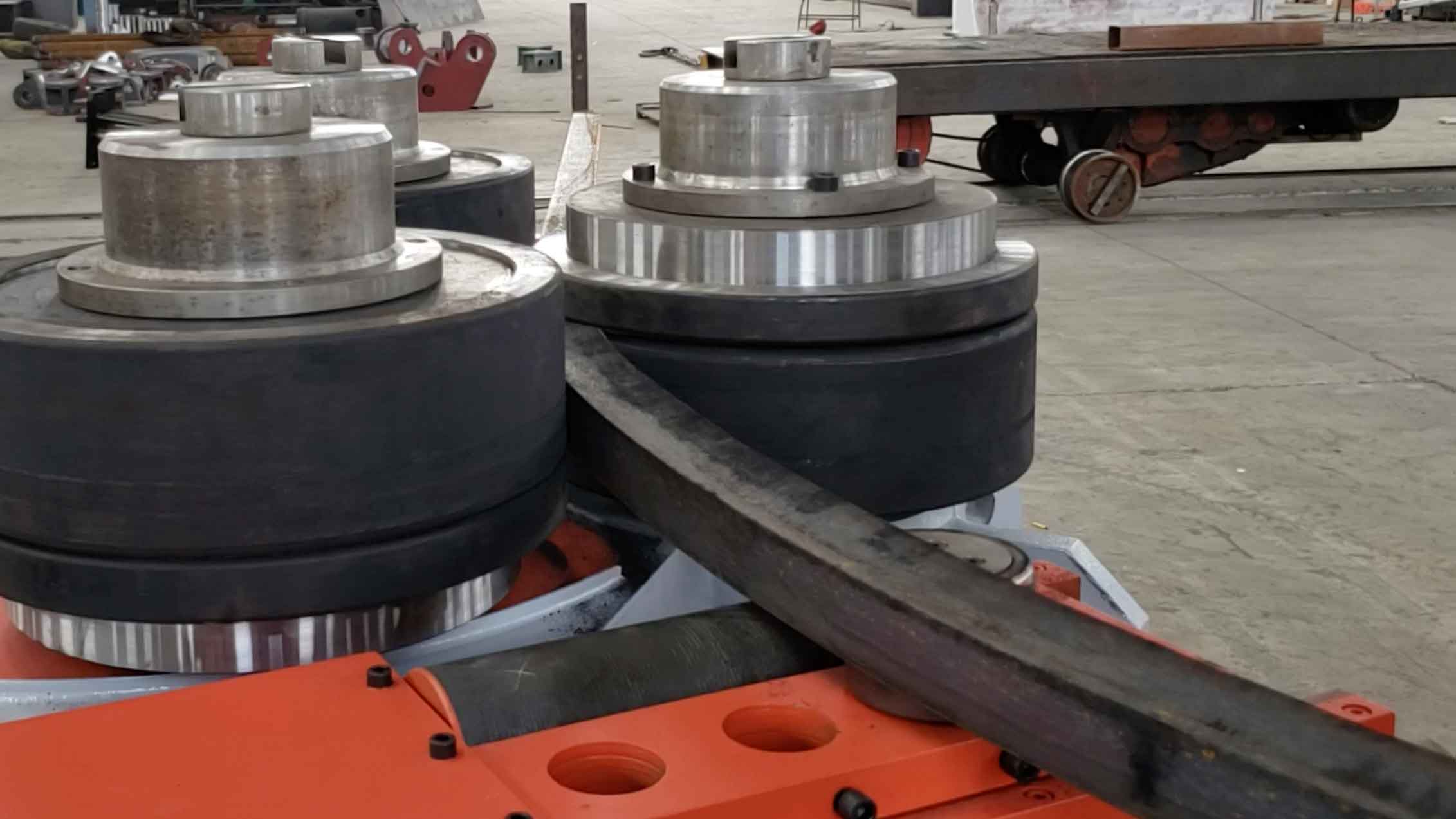
Let’s discuss the best type of heavy-duty double-clamping profile bending machine in the market: Two rear axes are driven by hydraulic systems to perform planetary motion. Both axes provide bending force to achieve pre-bending at both ends, resulting in minimal straight ends and enabling asymmetric bending. Since the repeat positioning bending accuracy for heavy structural profile components is not as critical, the only choice for providing substantial bending force is hydraulic motors.
The Bending Axis Diameter Determines Bending Capability
The diameter of the bending axis directly affects the bending capacity of the profile bending machine. The larger the diameter, the stronger the load-bearing capacity, allowing the machine to bend larger cross-sections and higher-strength profiles. The length of the axis impacts the support stability, with shorter axes being more suitable for high-precision bending. The material and heat treatment process of the axis determine its torsional strength and durability, affecting long-term bending accuracy.
A thicker, stronger axis increases bending capacity and is suitable for heavy structural components, while a thinner axis is ideal for high-precision bending of small or lightweight profiles.
Profile Bending Machines for Aluminum Extrusions
Due to the design structure of aluminum extrusion bending machines, they can only perform symmetric bending. Therefore, the diameters of the three axes (front and rear axes) are the same, and the driven axes on both sides symmetrically support the main shaft. During bending, the force applied to the profile is transmitted along a symmetrical path. This is especially suitable for symmetric profiles (such as round pipes, square pipes, symmetric U-shaped steel, etc.), as stress distribution is more uniform during deformation.
Profile Bending Machines for Heavy Structural Components
For heavy structural components, the main axis (front axis) diameter of the double-clamping profile bending machine is usually larger than that of the rear axis. This is because the main axis is directly driven for bending and not only transmits power but also bears the resistance of the profile during the bending process. As a result, it needs higher torsional strength, which is proportional to the fourth power of the diameter (T ∝ d⁴). The larger the diameter, the stronger the torsional strength. It also reduces deflection deformation during profile bending, especially when processing large, rigid profiles. It effectively reduces precision errors caused by axis deformation. (You might notice a significant difference between profile bending machines for aluminum and heavy structural components: machines for aluminum typically have deflection compensation devices at the top of the bending axis, while heavy-duty profile bending machines do not.)
Larger diameter main shafts are less prone to heating or fatigue cracking under continuous force, making them ideal for long-term batch processing of heavy-duty profiles (such as steel beams).
Y-Axis
In high-quality profile bending machines, the Y-axis adopts a structure with three main drive rollers. With all three rollers in a driven state, the profile bending machine effectively prevents slippage when processing small diameter profiles and generates higher torque to handle harder or thicker materials. This reduces rolling friction, improves machine efficiency, and lowers energy loss, making the entire bending process more efficient and stable. The machine effectively prevents uneven bending, surface cracks, or plastic deformation during the bending process, significantly improving forming quality and production stability.
X-axis and Y-axis
In Profile Bending Machines, the Relationship Between Torque on the Y-axis and Bending Force on the X-axis
The torque on the Y-axis and the bending force on the X-axis are interrelated but represent forces in different directions. Below is a detailed explanation of their relationship:
Bending Force on the X-axis
The bending force on the X-axis acts in the horizontal direction on the profile. It is typically applied through the compression action of two rollers in the horizontal plane, causing the material to bend. This force is directly related to the profile’s bending strength, section modulus (W), and the material’s yield strength (σ).
The bending force on the X-axis is mainly exerted by the upper or lower rollers (in a dual-roller design), with the goal of compressing the profile to achieve the desired bending radius.
Torque on the Y-axis
The torque on the Y-axis acts in the vertical direction on the profile, providing rotational or twisting force. During the bending process, the torque on the Y-axis alters the material’s shape via the rotation of the rollers, especially affecting the smooth transition of the profile at different bending radii. The magnitude of the torque influences whether the bending process is uniform, particularly when dealing with larger cross-sections or high-strength materials.
The Relationship Between the X-axis Bending Force and the Y-axis Torque
Coupling Effect: The bending force on the X-axis and the torque on the Y-axis work synergistically. Although they act in different directions, both jointly determine the final bending result of the profile.
The torque on the Y-axis provides rotational and deformation force, helping the material maintain shape consistency during X-axis bending, preventing slippage and excessive deformation.
The bending force on the X-axis provides compression force, directly impacting the bending radius and shape of the profile. If the coordination between these two forces is incorrect, it can result in uneven bending or cracks on the surface of the profile.
Interdependence: To achieve effective bending, the Y-axis torque and the X-axis bending force need to be precisely adjusted and coordinated. Typically, the machine must balance the output of these two forces according to the profile’s size, strength, and bending radius requirements.
The torque on the Y-axis and the bending force on the X-axis are two key mechanical factors in profile bending machines. The torque on the Y-axis provides the rotational force required for bending, while the bending force on the X-axis achieves the actual bending of the profile. Both work closely together to determine the material’s forming effect and accuracy during the bending process.
Z-axis – Three-dimensional Bending
In profile bending machines, the application of the Z-axis refers to the collaborative operation of three axes (X, Y, and Z) to perform more complex three-dimensional bending. The introduction of the Z-axis allows the machine to go beyond traditional planar bending (controlled by the X and Y axes) and apply forces in multiple directions, enabling the bending of more intricate curved shapes.
Role and Definition of the Z-axis:
The Z-axis typically represents a third direction, perpendicular to both the X and Y axes. In profile bending machines, the CNC-controlled Z-axis (guide roller) adjusts the vertical depth, enabling seamless bending of simple 3D parts and asymmetric profiles on the plane.
Three-dimensional Bending:
Three-dimensional bending combines control in the X, Y, and Z directions, allowing the profile to form spatial curves or simple 3D shapes during the bending process. For example, in the construction industry, profiles may need multiple adjustments in different directions to create curves, spirals, and other complex structures. In the automotive and aerospace industries, body components and special aluminum profiles often require three-dimensional bending to meet unique design specifications.
T-axis (Twist Axis)
Twisting (also referred to as off-axis bending) occurs when the profile deforms not along a single axis but rotates around its own axis. Strictly speaking, it is a rotation around the profile’s center axis, commonly represented as the θ (theta) axis or T-axis (Twist axis).
In engineering control systems, this is often considered the fourth axis (for example, A-axis or θ-axis, in addition to the X, Y, Z axes) and represents the rotation angle of the profile’s cross-section around its central axis in space.
Twist (Off-axis) Bending plays a crucial role in processing complex structural components:
- Manufacturing 3D bent components: In addition to bending in the XY plane, the Z-axis rotation is added to create complex geometries like spirals and twists.
- Simulating real-world installation conditions: For structures such as roll cages in automobiles or flexible conveyors, where installation surfaces are non-parallel or require twisting, off-axis bending is essential.
- Enhancing structural strength or aesthetic design: Some products need to be twisted along their axis to meet stress distribution requirements or achieve visual effects.
Axle Distance and Profile Bending Rolls
In profile bending machines, axle distance refers to the horizontal distance between the front axle and the two rear axles of the three-rolls, which typically determines the maximum bending width of the profile along the X-axis (i.e., in the horizontal plane). The larger the axle distance, the wider the span of profiles it can support, making it suitable for bending profiles with wider dimensions, such as large aluminum profiles or steel structural components.
The effective use length of the axles refers to the actual usable length on each roller axle where bending rolls can be installed. This parameter directly determines the thickness of the rolls that can be installed, thereby influencing the maximum allowable profile size in the Y-axis direction (i.e., vertically). In other words, the longer the effective use length, the thicker molds can be installed, supporting the bending of larger cross-section profiles.
Standard profile bending machines are typically equipped with a set of generic standard profile rolls that are compatible with commonly used square, rectangular, and other standard cross-sectional profiles, without the need for custom molds. In contrast, circular tubes (such as aluminum or steel pipes) typically require specially designed rolls with curved grooves to avoid slippage or deformation.
Axis Control and CNC Control System
In profile bending machines, precise control of each axis’ movement is key to ensuring bending quality and accuracy. The CNC control system not only regulates the precise movement of the X, Y, and Z axes but also ensures consistent shape and dimensions during the bending process by controlling the rotation and displacement of these axes. This is especially crucial when handling complex profiles or three-dimensional shapes, as the CNC system can precisely adjust the movement of each axis, ensuring that every bending action meets the set requirements.
CNC Control System and Axis Control
The CNC control system acts as the “brain” of the profile bending machine, controlling the rotation and movement of each axis. By importing 2D or 3D drawings, the system not only automatically generates processing paths based on the design but also precisely controls the movement of each axis. The precise control of each axis is essential for smooth transitions in bending and the accuracy of the shape. Whether it is through the X-axis applying horizontal bending force or the Y-axis providing vertical torque, the CNC system can accurately adjust the rotation angle and depth of each axis to ensure precise bending.
By importing 2D or 3D drawings into the CNC system, the design drawings are directly converted into processing paths, and the system automatically adjusts the movement trajectory of each axis based on these paths, avoiding errors in manual operation. This process essentially involves automatically controlling the rotation, depth, and angle of each axis to ensure perfect bending of the profile, improving production efficiency and reducing material waste.
Automation and Precision
The CNC control system not only enables precise control in batch production but also supports real-time adjustments. Factors such as material thickness and yield strength may affect the bending effect, and the system automatically compensates for the movements of each axis based on these data, ensuring consistency and accuracy with each bend. The operator only needs to import the design files, and the system will automatically complete the bending task, with precise and efficient control of the axes.
Through the intelligent control of the CNC system, the rotation and movement of the axes become more accurate, making the profile bending process both efficient and in line with design requirements, significantly enhancing production efficiency and product quality.
Greater Efficiency and Reduced Skill Requirements
All parameters can be input via the CNC system, including precise control of all axes (X-axis, Y-axis, Z-axis, and rotational axes). However, in practical operations, material thickness and yield strength may vary, and each discrepancy from the programmed parameters could lead to variations between the design and the final workpiece. To address these variations, some advanced profile bending machines feature real-time bending radius measurement and compensation functions, which can intelligently adjust the movement of each axis and processing parameters based on the material’s springback. This ensures consistent bending precision, effectively saves material, and significantly improves production efficiency.
Although CNC profile bending machines still require operator involvement, the operators no longer need to possess highly specialized bending skills. With precise control over the movement and bending process of each axis by the CNC system, once the program is set or the design blueprint is uploaded, the bending operation can run automatically. This greatly reduces reliance on skilled operators, allowing even less experienced personnel to perform complex bending tasks accurately without expert guidance.